The Challenge:
Place up to 140,000 cubic yards of tremie concrete to construct a 2,700-foot-long concrete dam across the Ohio River without draining the water.
The Players:
U.S. Army Corps of Engineers
Washington Group Alberici (WGA)
The Process:
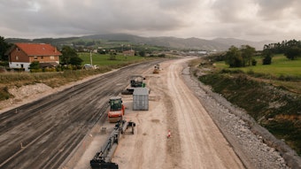
Located on the Ohio River that begins in Pittsburgh and flows west 981 miles to the Mississippi River at Cairo, Ill., are 20 locks and dams that provide a nine-foot deep year-round channel for navigation. The continued increase of water-borne commerce on the Ohio River has required periodic improvements in the waterways transportation infrastructure.
Two of the current locks and dams, nos. 52 and 53, originally built in 1929 and located on the Ohio River between Paducah, Ky. and Cairo cannot meet the current and future traffic demands without significant delays because of their age and dated design. As a result, the U.S. Army Corps of Engineers (the Corps) and the navigation industry are replacing locks and dams nos. 52 and 53, with one of the largest civil works projects undertaken by the Corps.
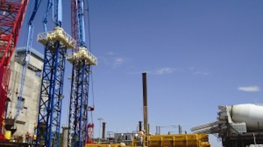
The joint venture Washington Group/Alberici (WGA) was awarded the $564 million contract from the Corps for construction of one of the last phases of the project, which includes constructing a 2,700-foot-long concrete dam across the river. The dam will comprise five 110-foot tainter gates and a navigable pass section with boat-operated wicket gates along with a fixed weir tying the dam into the Kentucky bank. Construction began in spring 2004 and the estimated completion date is December 2015.
The dam is being constructed using the in-the-wet method, a first for the Corps on a dam of this size. The in-the-wet method is the construction of a dam under water. Normally, the water is drained out of a cofferdam and the construction work is done "in-the-dry." The in-the-wet method was employed because the Corps was convinced this method would be cheaper, faster and have less impact on the environment than using conventional cofferdams.
"There is nothing standard about this job," says James Whitworth, marine engineer with WGA. "The in-the-wet method required us to think outside of the box to figure out how we would construct the dam underwater. We had to determine which equipment would be the most efficient in this unique job environment."
Because of the importance of everything working correctly for the entire length of every 36-hour pour, the mix design was reviewed and trial-run testing was carried out under cold-weather conditions to determine the level of pumpability of this "sticky" mix. The tremie concrete mix is self-leveling to ensure it fills up every square inch under the shell for ultimate strength. "The mix's strength is 5,000 psi at 90 days and has a 10-inch slump," Whitworth says. "It does not need any vibrating."
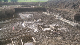
Precast shells are being constructed on land adjacent to the dam location and are being carried into position and set underwater on a prepared bed of select fill, piles and continuity rebar grids. Once the shells are in place, concrete is tremied under the precast shells to form a continuous bond between the piles, rebar, and surface shell and provide more strength and fuller foundation overall for the dam. Placing the concrete for each of the 28 shells is a non-stop 36-hour, step-by-step process. First, a truck-mounted concrete pump, located on the river side of the project, delivers the concrete through slickline across the lock chambers.
At the end of the slickline is the 31-meter placing boom that delivers the concrete into four stationary mixer drums on each of the two delivery barges. Next, the delivery barges go to the placing barge where stationary mixer drums dump the concrete into the remix hoppers. These two delivery barges constantly rotate between the 31-meter boom and the placing barge to provide the most efficient placement of concrete during the non-stop pours.
Two DVH 5/2 diversion valves are hooked up between the trailer pumps and the placing booms. "The diversion valves have been an added support of muscle within this system," Whitworth says. "They provide the flexibility to use either trailer pump with either placing boom, and provide cleanout routes. In addition, the valves can easily handle high pressures up to 1,885 psi without leaking."
After the trailer pumps and diversion valves, the concrete travels up to the two MX 43/47Z placing booms. It is then delivered to the tremie pipes that move it underwater to its final resting place underneath the precast concrete shells.
As of early January 2011, the concrete placing system had delivered 2,000 cubic yards of concrete for one precast shell. The system will deliver up to 5,000 cubic yards of concrete for each of the remaining pours and is estimated to be on site through 2015.
The Equipment
Putzmeister's Special Applications Business (SAB) helped decide what equipment would be best suited to deliver the tremie concrete. Equipment used for the placement process includes:
- Two freestanding MX 43/47Z-Meter placing booms mounted on two freestanding pin towers
- One 31-Meter placing boom
- Two BSA 2112 skid-mounted concrete trailer pumps
- One 40-Meter truck-mounted concrete boom pump
- Four Maxon Maxcrete IV 18-cubic yard (13.7m3) remix hoppers
- Two DVH 5/2 diversion valves


![[Video] Wacker Neuson 3001 Concrete Edition Dumper](https://img.forconstructionpros.com/files/base/acbm/fcp/image/2017/03/default.58c70968eb3be.png?auto=format%2Ccompress&fit=crop&h=135&q=70&w=240)