We often get questions from concrete contractors that relate to common and uncommon concerns. Here we discuss three such questions.
Clear cover for reinforcing bars used in slabs-on-ground
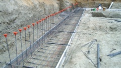
Plans call for a 5-inch-thick slab-on-ground with #5 reinforcing bars spaced at 12 inches on center each way with the surface of the top bar located 2 inches below the slab surface to help control curling as recommended in Section 14.9 of ACI 360R-10 ("Guide for Design of Slabs on Ground"). The building inspector states that reinforcing bars must have 3 inches of clear cover from the base as stated in Section 7.7.1 of ACI 318-08 ("Building Code Requirements for Structural Concrete") for concrete cast against and permanently exposed to earth. Earth isn't defined in ACI 318-08 so the inspector says he considers the granular base the slab rests on to be earth. As seen in Figure 1, there's a problem in meeting the inspector's requirement.

FIGURE 1. For a design slab thickness of 5 inches, requiring 3-inch cover to the bottom bar and 2-inch cover for the top bar leaves no room for the mat of #5 bars each way. Even if bars are placed at the tolerance extremes, the slab must be at least 5 1/2 inches thick.
With allowable tolerances, the 3 inches of clear cover can be reduced to 25/8 inches, and the location of the reinforcing steel can be reduced to 15/8 inches from the surface per Sections 2.2.2 and 2.2.1, respectively, of ACI 117-10 ("Specifications for Tolerances for Concrete Construction and Materials and Commentary"). Thickness of the two layers of #5 bars is fixed at 1¼ inches. So even if the bars are placed precisely to take maximum advantage of the tolerances, the slab must still be exactly 51/2 inches thick to meet the designer's intent for the top bars to be located 2 inches below the slab surface. There is no plus tolerance on slab thickness (ACI 117-10) so the contractor could plan on placing a 51/2-inch-thick slab.
In summary, meeting the inspector's expectation based on the engineer's design requires an extra half inch of concrete thickness if the steel is placed in an exact location (no tolerance) and the thickness is at least 51/2 inches. A change order would be required to reimburse the contractor for extra concrete costs, but the impossible task of placing the reinforcing steel and concrete slab with no tolerance isn't likely to happen. What now?
The first obvious solution to the problem is that ACI 318-08 does not apply to slabs-on-ground. Section 1.1.7 states this explicitly:
This Code does not govern design and construction of slabs-on-ground, unless the slab transmits vertical loads or lateral forces from other portions of the structure to the soil.
But what if the slab does transmit vertical loads or lateral forces from other portions of the structure? There is still a way to deal with this problem, as described in the Commentary for Section 7.7 of ACI 318-10:
Alternative methods of protecting the reinforcement from weather may be provided if they are equivalent to the additional concrete cover required by the Code. When approved by the building official under the provisions of 1.4, reinforcement with alternative protection from the weather may have concrete cover not less than the cover required for reinforcement not exposed to weather.
Because placing a vapor retarder immediately beneath the slab-on-ground can be considered as alternative protection, when approved by the building official, that solution is probably the best because it also restores the tolerances by allowing a depth of cover of 3/4 inches on the bottom of the ground slab. A change order would still be needed to cover the additional cost of the vapor retarder.
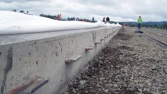
Glue-down flooring material on a 6-foot-thick base mat
The plans for a multistory structure called for a 6-foot-thick base mat. A 4-inch-thick concrete slab was to be placed on a vapor retarder resting on the base mat in preparation for installing a glue-down, moisture-sensitive floor covering. In a value-engineering move, the engineer decided to eliminate the 4-inch-thick slab and finish the base mat so the glue-down flooring could be directly applied to the mat surface. A question then arose as to the need for, and location of, a vapor retarder.
ACI 302.2R-06 ("Guide for Concrete Slabs that Receive Moisture-Sensitive Flooring Materials") recommends sandwiching the vapor retarder between the base course and concrete slab when a moisture-sensitive flooring material will be installed. In this case, though, the slab is 6 feet thick. Should the vapor retarder be placed at the bottom of the slab?
Placing a concrete floor slab directly on top of an intact vapor retarder helps to ensure that moisture from the base course or subgrade is isolated from the concrete. Once the moisture content of the concrete stabilizes as a result of drying, it may increase at the top of the covered slab as moisture moves up from the bottom. But if it reaches an equilibrium moisture content the flooring adhesive can tolerate, the flooring should perform well as long as no more water enters at the bottom of the slab as seen in Figure 2a.

FIGURE 2a. A 4-inch-thick floor slab, before drying, has an equilibrium relative humidity (RH) of about 100 percent (red line). With the top surface exposed to 50 percent RH air, an RH gradient develops, with the bottom concrete still at close to 100 percent RH (yellow line). After the floor surface is covered, a new and acceptable equilibrium RH of perhaps 85 percent (green line) is reached. The drying time needed for this is usually a few months.
Locating the vapor retarder in direct contact with the bottom of the slab makes sense when the slab is inches thick. But when it is 72 inches thick, the reasoning falls apart. Free water in most of the slab will take longer to rise toward the top of the slab. But it will rise until an equilibrium condition is reached. Unfortunately, the equilibrium condition is likely to be a higher one than the flooring adhesive can tolerate without re-emulsifying and causing a flooring failure as seen in Figure 2b. It's not water from the subgrade or base that causes the problem but free water contained in the capillary pores of the concrete. Thus the vapor retarder serves no useful purpose because there is too much water in the 6-foot-thick mat and the drying time needed would unreasonably extend the construction schedule.

FIGURE 2b. A 72-inch thick slab, with the top surface exposed to 50 percent relative humidity and dried for the same amount of time as the 4-inch-thick slab would probably still be at an equilibrium relative humidity of 95 percent (green line) or more. This is too high to permit good performance of most flooring adhesives but drying to an acceptable level would take many months.
But leaving out the vapor retarder doesn't solve the problem. Now water must be prevented from contacting the adhesive at the interface between the concrete and the adhesive. That requires a topical sealer on top of the base mat, or some other way to mitigate the potential flooring failure. Such moisture mitigation systems exist but can be expensive. The question now becomes which costs less: The original design with the 4-inch-thick slab placed on a vapor retarder or the base mat coated with a moisture mitigation system? The original design is likely to be the better choice. So be careful in dealing with such value-engineering decisions.
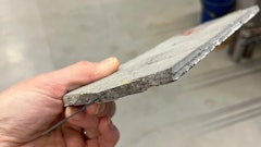
Random floor cracks
Random cracks in slabs-on-ground are a constant source of problems for concrete contractors. Specifications may require that cracks with widths beyond a given value be repaired. They may even require that every floor panel with a random crack be removed and replaced. In some cases, crack-free floors may be mandatory, for instance in a food processing plant. But for many floors the occasional random crack does not affect performance.
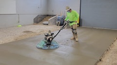
The rationale for the no-tolerance approach is that a crack is an indication of a construction flaw. Poor curing, inadequate sawcut depth for contraction joints, late joint sawing or a number of other reasons may be cited. This is an example of unrealistic expectations for concrete construction. Some owners, architects and engineers believe that perfection is possible in concrete construction. Other owners know perfection isn't possible but look for ways to keep some of the contractor's retainage.
It's interesting to note that two of the most authoritative American Concrete Institute documents, excerpted below, state specifically that some random cracking should be expected.
The Foreword to "Guide for Concrete Floor and Slab Construction (ACI 302.1R-04)" includes the following:
Application of present technology permits only a reduction in cracking and curling, not elimination. Even with the best floor designs and proper construction, it is unrealistic to expect crack-free and curl-free floors. Consequently, every owner should be advised by both the designer and contractor that it is normal to expect some amount of cracking and curling on every project, and that such occurrence does not necessarily reflect adversely on either the adequacy of the floor's design or the quality of its construction.
The synopsis for "Guide to Design of Slabs-on-Ground" (ACI 360R-10) contains almost identical wording:
Even with the best slab designs and proper construction, it is unrealistic to expect crack-free and curl-free floors. Every owner should be advised by the designer and contractor that it is normal to expect some cracking and curling on every project. This does not necessarily reflect adversely on the adequacy of the floor's design or quality of construction.
Section 3.2.5.3 of ACI 302.1R-04 gives more detail regarding the amount of cracking to expect:
For unreinforced, plain concrete slabs, joint spacings of 24 to 36 times the slab thickness, up to a maximum spacing of 18 feet (5.5 meters), have produced acceptable results. Some random cracking should be expected; a reasonable level might be random visible cracks to occur in 0 to 3 percent of the surface area floor slab panels formed by saw-cutting, construction joints, or a combination of both.
Despite these cautions, concrete contractors are often told to repair all cracks or remove and replace cracked panels, even though cracked floors may perform their intended function. If such requirements are contained in the specifications and the contract has been signed, there is little the contractor can do. But an attachment to the bid can take exception to the more stringent crack requirements by citing the ACI documents. And the documents may also be used to establish that the contractor following a normal standard of care does not preclude some random cracks.
Ward R. Malisch, P.E., is technical director for the American Society of Concrete Contractors. He can be reached at [email protected]. Bruce A. Suprenant, P.E., is the president of Concrete Engineering Services. He can be reached at [email protected].