Engineers at Astec Industries, a leading manufacturer of hot mix asphalt plants, needed to develop a new burner design quickly to accommodate a change in business strategy. Using the traditional build and test method, it would take six to 12 months to get the new burner to market, which would have put a crimp in the company's plans.
Instead, engineers used computer simulation to reduce the time needed to develop a new aggregate drying burner designed for use in asphalt plants to only 32 days. The burner needed to meet stringent requirements for highly efficient combustion and low emissions of NOx, CO and noise, yet there was barely time to build a single prototype.
The design team used computational fluid dynamics (CFD) to evaluate a large number of virtual prototypes and iterate to an optimized design. The most important concern was determining the best way to inject the fuel in order to obtain an ideal gas mixture.
CFD saved a huge amount of time by making it possible to visualize the flow and chemical concentrations throughout the early design iterations, providing far more information than could ever have been obtained from physical experiments. Within two weeks, the design team produced a credible working prototype, and within a month, the team optimized it to improve performance and meet the most stringent NOx and CO regulations. To date, 36 of these burners have been produced and they have delivered excellent performance for customers.
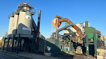
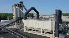
Astec Inc. manufactures a line of hot-mix asphalt plants and soil purification and environmental remediation equipment. The burner described here is used in an aggregate dryer used to remove moisture from rock so it will bind to cement to form asphalt. Astec previously purchased burners, but recently made the decision to design and build its own.
At the time the decision was made, the company had eight dryers nearly ready to ship but lacked burners. One of the requirements placed on the burners was that they perform equally well with natural gas, fuel oil, or propane. Another requirement was that they meet increasingly stringent regulations for emissions of NOx, CO and noise.
Astec's only previous experience was a single pre-mix burner built in 1993. This burner was designed using a traditional approach which involved building a series of prototypes, measuring their performance, and gradually iterating toward an acceptable design.
Using this approach, it typically takes six to 12 months to meet design objectives. This is because of the considerable time required to build and test each prototype and because physical testing provides only limited diagnostic information. Just about the only information that can be gained on the flow within the burner comes from drawing conclusions based on the shape and color of the flame, and from measuring the combustion emissions.
Simulation used from the beginning
Fortunately, Astec had previously established a CFD capability that made it possible to simulate the design of a burner ' or any other fluid flow problem ' and determine flow velocity, pressures and chemical species concentrations anywhere within the solution domain.
Astec engineers developed an initial premix burner concept design consisting of a centrifugal blower, fuel train and gas injection orifices, fuel and air mixing chamber, and a nose where combustion takes place. The advantage of a premix design is that air and fuel are mixed prior to entering the burner body, which results in a more intimate mixture and tends to lower emissions.
A major design challenge, however, is injecting the gases so that near-ideal mixing is achieved, because uneven concentrations of air and fuel will substantially increase emissions levels and reduce combustion efficiency. The fuel is brought into the mixing chamber in pipes arranged in a radial pattern, and holes are provided to inject the fuel into the chamber. The holes need to be arranged to provide as close a uniform fuel air mixture throughout the mixing chamber as possible.
Astec engineers addressed this and other design issues by modeling the burner using FLUENT CFD software from Fluent Inc., Lebanon, NH. The initial concept design was generated using the SolidWorks computer aided design system. Engineers imported the geometry into the ICEM CFD preprocessor where they generated separate CFD models for the blower, mixing chamber, and nose. They created separate models of different sections of the burner in order to focus on one part of the design at a time while reducing CFD solution times.
Several models were run in succession. The results of one were used as boundary conditions for the next.
The goal of the fan simulation was to obtain an even velocity distribution over the output cross-section. This goal was accomplished by adding directional vanes.
In the mixing chamber simulation, engineers moved the injection holes in order to achieve a swirling flow pattern that provided excellent mixing while also controlling the size of the flame to avoid damage to the drum. In simulations of the nose, engineers focused on generating small recirculation zones to hold the flame in place to maintain stability.
While the CFD simulations were being performed, Astec built and tested a prototype in order to validate the CFD predictions. The numerical results were found to closely match the experimental measurements.
Quickly moving to an optimized solution
The ability to quickly modify and solve the CFD models without making hardware changes made it possible to complete about two design iterations per day. Just 23 days into the design process, Astec engineers concluded they had a saleable product.
At about this time, the engineers created a combustion model to analyze the emissions performance of the engine. The combustion model for a 90-degree sector made use of 2.5 million cells, and took two days to solve.
The results turned out to be surprisingly accurate. It even predicted where in the flame envelope the highest concentration of NOx would occur. Testing on the pad confirmed the prediction to be accurate. The success of the design process was validated by the fact the initial NOx numbers turned out to be well below the toughest regulatory standards, as designed and predicted.
Since the design featured a variable speed combustion air fan, engineers also looked at how different fan speeds affected system characteristics such as the velocity distribution at the fan output, the fuel-air mixing and swirling patterns, and the combustion stability. At low speeds, engineers paid close attention to the potential for flashback by comparing the flow velocity at the burner to the flame speed. They have since used CFD to develop five additional models in sizes ranging from 30 million to 125 million BTUs per hour.
The resulting Phoenix Talon burner is designed for the tough demands of today's efficient aggregate and hot mix asphalt operations. It makes use of premix gas burning technology and advanced air-atomized, nozzle mix oil burning technology to provide high efficiency and low emissions.
The operator has only to change the excess air level via the controls to operate in the lean-burn range, meeting emissions regulations that require no difference of configuration from the base unit. The use of a variable speed combustion air blower, instead of a traditional damper, results in lower power consumption and fewer parts to potentially break or get out of adjustment. The final product has been an unqualified success in the field.
For more information about CFD software, visit www.fluent.com. For more information about Astec, e-mail: [email protected].