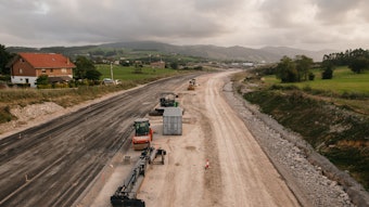
A massive construction project has been underway deep in the heart of the Schnecktal valley area in Germany. The majority of the work is underground, as a joint-venture team led by German contractor Wayss and Freytag Ingenieurbau AG builds the nearly 4.3-mile-long (7 km) Finne Tunnel. Finne Tunnel is just one section of a new 76-mile (123 km) high-speed rail link between the cities of Leipzig and Erfurt, Germany.
Initial construction on the twin-bore tunnel began in April 2008. Two tunnel boring machines (TBMs) worked at the same time boring the 35.4-ft. diameter (10.8 meter) shafts. Peak TBM production rates reached up to 80 ft. (24.5 meters) per day. The internal, lined diameter is 31.5 ft. (9.6 meters) and was formed using precast concrete lining segments or rings. They were cast on site and each ring was 6.6 ft (2 meters) long, 17.7 in. (450 mm) thick and weighed 12 tons. A total of 6,822 rings were needed to line the new tunnels.
In September 2009, the first TBM "holed through." The second one followed it a few months later when it broke through in February 2010, six months ahead of schedule. Work was far from being completed, however. It was time to start the slipforming phase within the tunnels.
Paving in Circles
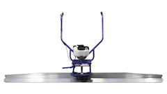
Representatives from Wayss and Freytag worked with Gomaco International Ltd. to determine which paver would suit their tunnel applications. They chose the Gomaco Commander III. The slipformer would first pave the tunnel floor in four-track mode, then be converted on site to a three-track paver to slipform the tunnel's walkway.
The decision was also made early in the design phase to use a Leica Geosystems 3D control system. Setting and maintaining stringline within the tight confines of the tunnel would be nearly impossible, and the stringless system would alleviate those concerns.
The concrete for the various tunnel applications was provided by an on-site mobile batch plant with a 105-cu.-yd. (80 cu. meter) per hour capacity and is located just outside of the tunnel entrances. A dry, low-slump concrete was produced with a low percentage of cement.
"We had concrete with less cement because of the size and depth of the applications," Christian Korndörfer, project manager for Wayss & Freytag, explained. "The floor is over 3.3 ft. (1 meter) thick. We didn't want the concrete curing process to generate too much heat inside the tunnel or result in any cracking within the concrete."
Delivering concrete to the paver within the circular tunnel was also a concern. Wayss & Freytag wanted to use standard concrete trucks, but having them drive in reverse through the length of the tunnel to reach the paver would be too time consuming. There was also no room inside the tunnel for trucks to turn around.
The company developed a two-part solution. The floor of the tunnel was paved in a special sequence. A weekly paving production goal of 3,281 ft. (1,000 meters) was established, with an average paving goal of 820 ft. (250 meters) per day. At the beginning of each week, the four-track Commander III was set up to pave 3,281 ft. (1000 meters) beyond the section of floor completed the week before.
The concrete trucks drove in forward gear on the completed tunnel floor to a turntable at the end of the section. The turntable then rotated the three-axle trucks 180° so they could drive in reverse to the paver, dump their load of concrete in front of it and then drive out of the tunnel in forward gear. Between six to eight trucks carrying 10.5-cu.-yd. (8 cu. meter) loads of concrete transported the material.
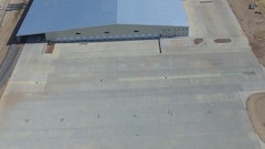
"The tunnel floor is 19.7 ft. (6 meters) wide," Korndörfer said. "In the circular tunnel, at its deepest point in the center, the floor was 41.3 in. (1,050 mm). We turned all four tracks on the Commander III to 35° angles so the paver could drive on the round walls."
The slipform mold was designed for a drainage channel in the tunnel floor. The channel measured 7.1 in. (180 mm) deep and 28.3 in. (720 mm) wide at the top tapering down to 21.3 in. (540 mm) wide at the bottom.
A height tolerance had to be met on the new tunnel floor to ensure the accurate installation of the future track rail. Control measurements confirmed the new concrete tunnel floor was always within the specified height tolerances.
"The achieved vertical accuracy of +/- 0.1 in. (3 mm) by far outperformed the required accuracy of a maximum +/- 0.4 in. (10 mm)," said Baumgartner.
In total, 36,623 cu. yds. (28,000 cu. meters) of concrete was slipformed in each 4.3-mile-long (7 km) tunnel to build the tunnel floor. Both production and quality of the finished product exceeded expectations.
100% Accuracy Required
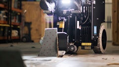
The second phase of slipforming involved Wayss and Freytag converting the Commander III to a three-track paver to slipform a walkway against one wall of each tunnel.
"The line of the train track must be 100% accurate and its placement is considered sacred," Korndörfer said. "The walkway mold had to be able to accommodate the changing alignment of the tunnel, tunnel superelevations and other variations created when working inside a tube."
Gomaco engineers designed and built a variable-height, variable-width walkway mold and hopper to accommodate the varying line of the tunnel. As the face of the tunnel wall changed, the mold compensated by telescoping in and out or up and down to change the size of the walkway and keep the profile in correct alignment to the train tracks. The telescoping feature also ensured the mold was always kept against the tunnel wall and the accuracy of the walkway placement maintained.
The top width of the walkway varied between 3.4 ft. (1.05 meters) up to 5.7 ft. (1.75 meters). Height of the walkway was also variable from 23.6 in. (600 mm) up to 37.4 in. (950 mm). Hydraulic pressure-compensated cylinders controlled the changes. A finishing roller, mounted to the back of the mold, helped provide the finish to the walkway's surface and eliminate the need for hand finishing.
A service channel in the surface of the walkway profile was slipformed 3.3 in. (85 mm) wide by 2.8 in. (70 mm) tall. Lighting conductor strips will eventually be placed in the keyway, tested to make sure they are operational and then covered and sealed. The keyway allows the strips to be removed and replaced as needed without damaging the profile of the walkway. A 2% cross slope across the top surface ensures proper water drainage off the walkway.
"The walkway was a much more challenging profile to slipform than the tunnel floor," Korndörfer explained. "It had to be placed with 100% accuracy and the Commander III slipformed the walkway very well. We had no problems and were able to achieve production rates from 558 to 656 ft. (170 to 200 meters) per day."
Wayss and Freytag was on schedule to complete its portion of the Finne Tunnel by the end of 2011. Other contractors will then start work placing the track and installing the electrical and other systems. The entire Erfurt to Leipzig line will be operational in 2015 and will be part of a high-speed connection from Munich to Berlin, Germany. Ultimately, the line will run all the way from the countries of Scandinavia to Italy.