We have all heard the saying “concrete can be counted on to do two things — get hard and crack.” Without thoughtful human intervention that saying might be true, but today slabs-on-ground can be engineered to resist unplanned cracking. Some slab shapes, however, are very susceptible to cracking, and that’s the subject of this article.
The shape and size of a slab or panel has much to do with susceptibility to cracking. Square shapes, for example, resist cracking the best, while rectangles with long, narrow sides and odd-shaped panels with interior corners are the most at risk.
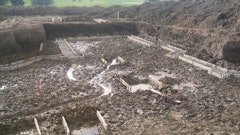
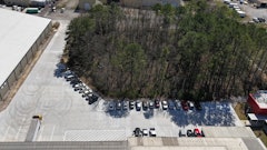
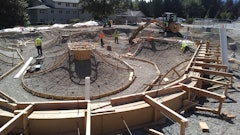
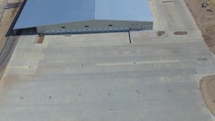
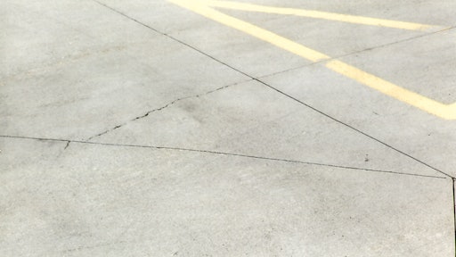
 This is an example of poorly laid out joints for a parking lot. The contractor was lucky to not have cracks crossing the many acute angles.
There are some joint configurations and panel shapes that require special attention. These include joints coming together in the shape of a "T," long and narrow rectangular panels, panels with an inside corner, and locations where two or more joints intersect at odd angles. The focus here is to provide information about how to lay out joints to redirect stresses that develop in concrete as it shrinks during the drying process. Some suggestions for designing concrete mixtures with reduced shrinkage are also included.
T-shaped joints
 Fig. 1 If T-shaped joints can't be avoided, drill a hole at the intersection of the joint.
 Fig. 2 If T-shaped joints cannot be avoided, provide supplemental reinforcing perpendicular to the terminating joint.
- Cut two lengths of #4 (1/2 inch diameter) rebar 3 feet long.
- Locate the first bar 1 inch below the paving surface and place it 1 inch from the intersecting joint, parallel to the top of the T.
- Place the second bar parallel to the first bar and 1 inch beyond (see Figure 2).
Narrow panels
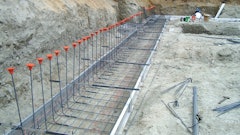
 Fig. 3 For long, narrow panels, place rebar at 0.5% of the cross sectional area of a slab.
Inside corners
 Fig. 4 With inside corners, if there are no joints going to the corner, place two #4 rebars 3 ft. long diagonal to the corner an inch away.
 Fig. 5 With an inside corner, when there is one control joint meeting the corner, place reinforcement as shown.
 Fig. 6 When two control joints meet at an inside corner, place reinforcement as shown.
When control joints intersect at an angle
 Fig. 7 When two or more control joints meet at a point, no angle should be less than 60 degrees, but 90 degrees is better.
When control joints meet curving form lines the joint should meet the formed edge at a 90 degree angle. Intersecting joints should be located a minimum of 18 inches from the formed edge of the slab or curb (see Figure 8). The full depth of the sawcut should be maintained until meeting the formed edge.
 Fig. 8 An example of three control joints coming together at one point and meeting a formed edge.
Additional considerations
There are additional considerations that can affect whether concrete develops cracks. The condition and preparation of the sub-grade is important. If there is ground settlement or frost heaving due to lack of water drainage under slabs, the resulting concrete stresses can cause cracks.
Some contractors include high dosage levels of fiber reinforcement, steel or synthetic macro fiber, in their concrete to help prevent cracking in all panel shapes. Steel fibers placed in the range of 70 pounds per cubic yard or synthetic macro-fibers at 7-1/2 pounds per cubic yard of concrete reduce both shrinkage and curl in panels. Experimentation by some contractors suggests that greater sized panels also are possible with the use of steel or macro fibers.
 This graphic demonstrates how to lay out joints under unusual circumstances.
Using well-designed concrete mixes reduces shrinkage also. Kevin MacDonald, president of Beton Consulting Engineers, Mendota Heights, Minn., says the amount of water is key when designing concrete mixes for floors and other slab-on-grade applications — not the water-cement ratio but the total amount of water added per cubic yard of concrete. Water has a direct relationship to both shrinkage and finishability. “The shrinkage factor when 250 pounds of water is added for a cubic yard of concrete is 1 and that’s acceptable. Adding 300 pounds of water yields shrinkage factors of 1.5 to 1.8 and that isn’t,” he adds. Rather than adding additional water to the mix in the field to enhance workability, both mid-range water reducers and polycarboxylate super plasticizers can be used to enhance placability while helping to control total water amounts for interior slabs and exterior slabs.
Shrinkage can also be reduced by increasing aggregate sizes to 1-1/2 inches or more and optimizing aggregate gradations because there is less total aggregate surface area to coat with cement paste. But local aggregate sources must be considered as well as slab thicknesses when making these decisions.
The amount of sand or fine aggregate has a large influence on finishability — too much sand makes concrete difficult to finish. Cellulose-based viscosity modified admixtures (VMA) can be used to replace some sand in a mix to make finishing easier.
Finally, don’t base decisions about concrete mixes by their strength alone — high strength concrete slabs usually shrink more if the higher strength is obtained by increasing the cement content.