The challenge:
Construction concrete transition structure tunnels under the Union Pacific Rail Yard in Denver.
The players:
BT Construction
Wylaco, Inc.
Griswold Machine & Engineering (GME)
The process:
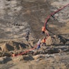
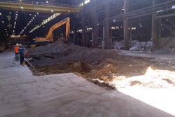
The High Street Outfall Project for the city and county of Denver consisted of side-by-side 96-inch-diameter storm tunnels under the Union Pacific Rail Yard, each 400 feet long. On both sides, a Y-shaped concrete transition structure was to be constructed, tying the twin tunnels into a single box culvert. Crossing under 17 sets of rails with the tunnel inverts 27 feet below grade in a sandy material, contractor BT Construction of Henderson, Colo., elected to construct the tunnels utilizing an Akkerman Microtunnel Machine. The first major hurdle was how to shore the jacking and receiving pits.
To meet the requirements of constructing both the tunnels, the jacking pit excavation had to have minimum inside dimensions of 40 feet wide, 48 feet long and 28 feet deep. Furthermore, the bottom 16 feet of the excavation had to be free of any cross supports to facilitate the construction of the cast in place structure. This excavation had one additional complexity: the front side of the pit had to be placed only 27 feet away from the nearest railroad track, dramatically increasing the load rating requirements of the shoring system.
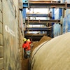
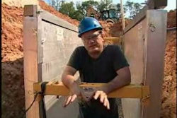
In addition to the load ratings of an excavation that close to rails, one requirement of the railroad is the constant support of soil during excavation. BT Construction turned to Wylaco, Inc., a local representative for the Griswold Machine & Engineering (GME) sliderail system. A slide rail system is a dig and push style system. With its modular, flexible design, the system can comply with a wide variety of shapes and sizes. Installed from the top down and removed from the bottom up, the system minimizes excavation size, soil disturbances, restoration time and cost. Installation is done with low vibration, providing soil support for excavations, adjacent structures and existing utilities.
Prior to excavation, four corner posts and four additional linear posts were installed. The first of three strut carts was then installed, followed by the panels. As the excavation progressed, additional panels and strut carts were added, ensuring that the adjacent soil was supported at all times.
One last obstacle remained in the preliminary design of the shoring. The concrete transition structures were 16 feet tall and no cross supports could conflict with the structure. In normal instances, sacrificial beams would be placed in an X on the floor of the pit prior to raising the strut carts. However, this design did not meet the required load ratings. BT hired a structure engineer to collaborate with GME’s engineers to find a solution to the problem. In the end, concrete supports, 3 feet by 2 feet by 4 feet were constructed in an X under the final grade of the structures, connecting and supporting the linear posts. This allowed the top strut cart to be removed and the bottom two raised to gain the necessary clearance for the structure. Because the bottom panel in the front wall also had to be raised for the construction of the tunnel, GME incorporated sheetpile into its design allowing BT to raise the bottom panel while still supporting the excavation.
After the preliminary designs were complete, the project was thrown a curveball. Another project, adjacent to the High Street Outfall, was underway and the completion of the transition structure on the receiving side was integral to the other project’s critical path. The city of Denver asked BT and GME to come up with a plan to construct both the jacking and receiving pits at the same time, thus expediting the completion of the structure. While it was a stretch to construct one pit of that size with the available equipment, two was not feasible. To solve the problem, BT worked with GME and Wylaco to come up with a pit of slightly smaller dimensions – 40 feet long and 36 feet wide - to better utilize the available resources. Engineers were also able to design one strut cart to have the capability of being modified in the field and be used in both pits at different phases of the job.
The designs for each pit were reviewed at length by BT and the owner. Once approved, the shoring plan drawings and calculations were submitted to the city of Denver’s design engineer. Passing his review, the design was sent on to the Union Pacific for their final acceptance. With construction being so close to the railroad’s yard, Union Pacific was careful to scrutinize the shoring design, ensuring that it met all the requirements of excavation. GME’s final design was approved without comments.
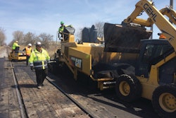
Both pits were excavated with ease, the shoring system performing perfectly. Following the excavation, the front walls, concrete supports and thrust walls were constructed in the jacking pit, facilitating the setup and use of the microtunnel machine. Shoring will remain in use though spring 2014, and the project is expected to be complete July 2014.