Sports enthusiasts know that when it comes to a fast ride, smoothness is key. It’s no secret that NASCAR drivers and motorsport enthusiasts prefer asphalt for this very reason. So in 2008 when the National Corvette Museum in Bowling Green, KY began toying with the idea of building a recreational motorsport facility to draw enthusiasts to the location, they knew asphalt was the way to go.
The 3.1-mile track was designed to provide a place for motorsports enthusiasts to come and safely drive their cars and motorcycles at speeds they couldn’t legally do on the road.
“We were looking at other ways to expand the reach of the Corvette Museum,” says Mitch Wright, general manager, NCM Motorsports Park. “From 2008 through 2012 we conducted feasibility and economic impact studies, and it was determined that our enthusiast base and location would bode well for the use of the facility.”
From the ground up
Scotty’s Contracting & Stone, based in Bowling Green, worked with the design firm from day one. “We wanted to get this thing as close to perfect as we could,” says Mike Law, project engineer at Scotty’s. “It started in the planning and design stage, working hand-in-hand with the designers to make sure that the track was constructible, that it would drain. We did a lot of work up front, focusing on the design part to make sure that was right first. A 3D model was constructed and we used that to do the grade work and some of the paving.”
Scotty’s broke ground in June 2013 to excavate the 186-acre area allocated for the track, paddock areas and skid pads.
“We had about a ½ million cu. yds. of dirt to move,” says Chris Higgins, surveyor at Scotty’s. “We actually started construction before the design was complete and used GPS machine control.”
Scotty’s crews input the job information into Trimble’s Business Center - HCE software that transforms a design into a 3D site plan. Crews started moving bulk materials in areas they knew would be close to grade, even if final plans weren’t available.
“We used a great deal of machine control,” Higgins says. “With the way the design changes came in, we were constantly modifying the site during the project.”
The software easily handled revisions to the site plan, which was updated on each machine by way of wireless signals. The changes could be made without a word of communication between Scotty’s central office, the on-site foremen and machine operators. “Those kinds of changes would not have been feasible with staking,” Higgins says. “We had about 15 pieces of automated equipment in here at one time. We would just make the changes on the site plan and they would be incorporated into all machines.” The machine operators would then work to the updated design.
“3D machine control really helped us with the speed of the project. We had about 90% of the dirt moved by November 2013. Given the weather we had last summer, that’s a pretty good speed. That allowed the ground to settle, which over the long run will pay huge dividends. It also helped us find areas that held water. We provided some additional drainage without having to impact the subgrade.”
The GPS and total station controlled the scrapers and dozers and made even the rough grading work considerably more precise, a solid start to help reach the more precise tolerances later on.
“During rough grading, the dozers installed with Cat Accugrade 3D grade control worked to within tolerances of tenths of a foot,” says JD Weis, general sales manager with SITECH Mid-South, which specializes in the sale of Trimble products and works withheavy equipment dealers of all braks to support technology needs. “Then machines equipped with 3D Total Station based Cat AccuGrade systems were used to complete the more accurate grading, down to hundredths of a foot.”
Mix masters
Due to the extreme need for a smooth track, a lot of planning went into creating the asphalt mix for this project. At high speeds, any type of bump can upset a car or motorcycle. Wright says the quality of surface can make or break a track, and first impressions are important.
“Unlike a highway, we’re dealing with more shear forces than the up and down pounding you’d get on an interstate,” says Wright. “We required a mix that would give us a really good wet weather grip, good resistance to unraveling, a good grip to the tires and one that is long lasting.”
Brian Prowell principal engineer at Advanced Material Services, who has done extensive work with mix design on racetracks across the country, was called in with his company to assist with developing the asphalt specifications and to provide quality assurance testing during construction.
“We typically use a 9.5 mm (3/8”) mix for the surface on a racetrack,” Prowell says. “We think this nominal maximum aggregate size (NMAS) is most resistant to raveling or loss of aggregate, which is the most common failure on a track. We also have to consider the friction wear characteristics of the aggregate. We do not want the aggregate to polish. We want it to provide a consistent grip with time.”
The mix they chose was a Marshall design to achieve a higher asphalt content which promotes cohesion, along with a heavily polymerized asphalt to help prevent raveling. A mix with PG 64-22 binder was laid for the 2-inch base course and a mix with a highly modified polymer PG 82-22 binder mix was then used on both the leveling course (1 1/2-inch) and the wear course (1 1/2-inch).
Knowing how critical the mix was, Scotty’s started the design from scratch. “It was a different type of mix than the Superpave we traditionally produce,” Law says. “We really focused on the materials. We needed to make sure we had good quality aggregates that not only provided the skid resistance, but provided what we hoped would be the proper grip and tire wear for the job.”
The aggregate source that was selected was not readily available in a size to produce a 9.5 mm NMAS mix, so the design gradation was adapted to a fine-graded 12.5 mm 1/2-inch NMAS mix.
The liquid asphalt was also a challenge, says Law. “The highest grade of liquid asphalt typically used in Kentucky is a PG 76-22. What Brian Prowell spec’d for this job was a PG 82-22 with a 180°F softening point. This took about double the amount of polymer than a typical PG 76-22 we would see.”
Scotty’s was able to design and produce the PG 82-22 liquid asphalt at the terminal they own.
All in all, 20,000 tons of the special track mix was used on the project; 60,000 total tons of mix was used to complete paving.
Pave to perfection
Understanding how to deal with this unique mix presented the crew with a new set of challenges. “The mix cooled off very quickly and stiffened immediately,” says Law. “We had a very small window for compaction and had to make sure the rollers were right up behind the pavers and got it compacted as soon as it was laid.”
The mix was also not very forgiving. “The high polymer content mix did not allow for much hand work at all,” says Law. “If any had to be done, the area needed to be reheated with torches and a lot of care had to be taken to make sure it looked right.”
Crews also could not walk behind the paver or their footprints would leave permanent blemishes in the surface.
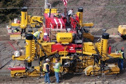
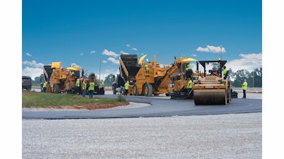
The paving crew of 20 people worked on two Cat AP1055D and AP1055E asphalt pavers to lay down the mix. The pavers worked side-by-side to create a hot-on-hot longitudinal joint. The two Weiler E2850s that transferred the mix to the pavers also provided re-mixing for temperature uniformity and elimination of segregation.
The track width was typically 36 ft. The lead paver worked at a width of 16 ft. and the second paver worked closely behind the first paver at a width of 20 ft. Average paving speed was about 15 fpm, based on hourly tonnage, paving depth and paving widths.
The relatively low paving speed allowed the pavers to move continuously and not out-run the trucking. That pace also allowed the compactors to match the pavers’ production.
“Paving in echelon was a big thing,” Law says. “We had joint density specifications, but the best thing to do for the quality of the project was to put two pavers out there in echelon and eliminate those cold joints in the middle.”
Technology paves the way
The crew also used 3D paving on the paddock areas that were constructed to create a “reconfigurable” racetrack for autocross courses or drifting.
“That was a bit of a unique challenge because it’s hard to get smoothness across the joints in that large of an area,” says Higgins. “It’s difficult and we had great success on accomplishing the design with the 3D paving.”
Because Scotty’s technology team was used to working with Trimble’s Business Center - HCE software, making the step to 3D paving was accomplished seamlessly.
The models automatically generate uncompacted surface designs for the 3D paving system. As the final step in executing the construction of the race course, the designs guide the paver to make adjustments automatically that place slightly more material above low areas and slightly less material in high areas.
The 3D paving system piggybacks on the Cat paver’s conventional 2D grade control system. The design file is stored in the control box installed on the screed. The technology team installed a mast with a prism (target) on top on the right side of the screed. There is also a slope sensor on the bottom of the mast.
Trimble Universal Total Stations located strategically around the site, tracked the prisms as the pavers moved around the race course. The Universal Total Stations send a constant stream of signals with precise measurements (accuracy within thousandths of a foot) to a the prism on the screed. The prism relays those measurements to the controller where they are compared to the master design file calculations.
If elevation corrections are needed, the commands are sent through the conventional 2D grade control system — to the right tow point in this instance. The left side of the screed is under slope control, using the calibrated slope sensor.
As the pavers move forward, the prism is picked up by other the next Universal Total Station on the jobsite to ensure constant 3D connections. A total of ten stations were utilized on the site to ensure the paver could do a single long run.
One of the benefits of the 3D paving system was its ability to use slope control on the joint match side of the trailing paver screed and have consistent height match. This accomplishment underscores the speed, accuracy and inter-connectivity of the Trimble system.
Scotty’s had not used 3D paving before on other jobs, just 3D milling and grade control, but will continue to use it based on cost savings alone. Scotty’s estimates GPS and 3D technology probably contributed to a cost savings of a quarter of a million dollars, just on engineering alone.
Scotty’s was given a deadline of July 12 to complete the paving work and finished on June 28.
Quality that speaks for itself
As far as checking for density, the crews were able to use the intermediate leveling course to ensure they were meeting specs without coring the precious surface.
“We like to place three layers on a track,” says Prowell. “Each layer offers the opportunity to improve smoothness by as much as 65%, although 30% is probably more realistic. We like the intermediate and wearing courses to be the same mix, if possible. We do this because then we can calibrate our density gauges with a number of cores on the leveling course and not core the surface.”
Scotty’s used a non-nuclear density gauge to check the quality of the leveling course mat. Prowell’s crew used a nuclear gauge and the separate readings were then correlated. Given that the mix for the surface course was to be the same, the crews felt comfortable with the density numbers on the leveling course such that they didn’t need to re-core the surface.
“For good performance, everything needs to be perfect for a track,” Prowell says. “The asphalt binder needs to be right, the mix needs to be right, it has to be compacted to good density and have good texture. Handwork needs to be minimized to end up with good texture/prevent raveling with the high polymer content, and finally, it needs to be smooth.”
This tediously constructed recipe for paving a smooth racetrack was certainly achieved, and Wright hopes the results speak for themselves. “If the track is rough or bumpy, that’s what it becomes known as. If you’ve got an extremely smooth surface, that’s again, just a huge added benefit to us at the museum,” says Wright.
“This is probably one of the best race track paving jobs I’ve been involved with,” Wright adds. “The surface is incredibly smooth. Scotty’s really went above and beyond and did a fantastic job.”
“It’s a project we’re very proud of,” Law says. “I think it turned out as close to perfect as we could get it.”
The multi-configuration race track with paddocks has a two mile west track, a one-mile east track circuit which can be run independently, a 2.85-mile outer loop and finally the full 3.125-mile track.
The track received its finishing touches and opened August 30 in conjunction with the Corvette Museum’s 20th anniversary celebration.
When the track is not rented out by racing enthusiasts, the facility will also serve as an educational center with highway survival programs, fleet training, law enforcement training and a high performance driving school