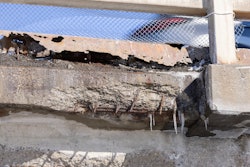
In liquid-bearing concrete structures, joints are where protective linings fail first. A monolithic film is asked to span a moving gap and stay bonded to both sides through thermal swings, settlement, hydrostatic loads, and start-stop operations. Over thousands of cycles, stress concentrates at the arris; micro-pinhole strings and edge-shear accumulate until the first callbacks show up — always at joints.
You can specify tougher chemistry, but method beats material at joints. The fix is to decouple movement from the film with a reinforced, compliant detail that's anchored on each side and to verify the work with standards-based QC that prevents expensive do-overs. Editors Note: find a troubleshooting guide as well as a "Spec and QC Cheat Sheet" at the end of this article.
Why Joints Beat Monolithic Films (Quick Mechanics)
Differential movement. Adjacent pours and wall-to-slab interfaces move independently. Typical thermal expansion alone in a 100-ft. wall across a 20° F swing produces approximately 1/8 in. of movement. Repeat that across seasonal and operational cycles and fatigue is inevitable — especially where you've got foundation settlement, soft soils, or structures built on expansive clay.
Stress concentration. Continuous films focus strain at sharp edges where small flaws become crack starters. Even a microscopic imperfection in surface prep becomes the failure point when subjected to thousands of movement cycles.
Fatigue and adhesion limits. Even high-elongation elastomers fatigue under cyclic shear at joint interfaces. Rigid films split or debond. The coating chemistry might be excellent, but physics wins every time when movement concentrates at a single point.
The Joint-Integrated Detail (What Actually Works)
Instead of trying to glue two moving parts together and hoping adhesion holds, a joint-integrated detail creates a controlled chase and bridges it with reinforcement that's fully wetted with resin and tied into the field coating. Movement happens beneath the lining; the composite bridge carries strain without pulling the coating apart.
Core Elements of the Detail
- Controlled chase. Route or sawcut the joint to specified depth and width; square edges, clean thoroughly, and vacuum out all debris.
- Moisture-compatible primer. Use an epoxy primer compatible with site moisture conditions (see moisture verification steps below).
- Bonded reinforcement. Place geotextile (for higher movement) or fiberglass mat/woven roving (for moderate movement) with a compatible wet-out resin. Ensure full saturation — no dry weave, no trapped air. Maintain specified overlaps across the joint, commonly 6-12 in. on each side of the centerline.
- Epoxy surfacer. Apply an epoxy surfacer to create a smooth, pinhole-resistant base that feathers cleanly into field areas and eliminates ridges.
- Elastomeric lining. Spray or roll the topcoat to specified dry film thickness (DFT), maintaining continuity across the reinforced zone.
Crew Tip: Treat joint zones as their own "mini-project." Keep separate wet film thickness (WFT) and DFT logs, pull-off adhesion records, and holiday test documentation for these areas. This level of detail stops arguments during final inspection and protects your warranty position.
Field Installation Sequence (Step-by-Step)
1. Survey and Planning
Walk the entire structure before any prep work begins. Identify all construction joints, control joints, expansion joints, wall-to-slab intersections, corners, penetrations, and prior repairs. Note any areas where you've already seen cracks or movement during the concrete work.
Estimate expected movement based on structure geometry, climate exposure (are you in Arizona or Minnesota?), and substrate conditions. If the structure sits on expansive clay or soft soils with documented settlement, plan for higher-movement details.
2. Moisture Verification
This step prevents 90 percent of premature failures. Measure concrete moisture with ASTM F2170 (in-situ relative humidity) and/or ASTM F1869 (moisture vapor emission rate). Document these readings before any primer touches the concrete.
Decision matrix:
- Readings within primer manufacturer limits → proceed with standard epoxy primer
- Elevated moisture but time-constrained schedule → use moisture-tolerant or MVB (moisture vapor barrier) qualified primer
- Readings way over limits → implement drying protocol or mitigation strategy; don't gamble on this
3. Surface Preparation
Prepare concrete surfaces per SSPC-SP13/NACE No. 6 to the specified ICRI Concrete Surface Profile (CSP). For most elastomeric systems, you're targeting CSP 3-5, which gives you that medium-to-coarse sandpaper texture.
Document the profile with comparator chip photos. Remove all laitance, loose material, contaminants, dust, and soluble salts. If you're working on a rehab project, pay extra attention to removing old coating residue and failed material at joints.
Reality check: Joints are the hardest areas to prep properly. Tight spaces, uneven surfaces, geometric complexity — all conspire against you. Budget extra time here; shortcuts at this stage guarantee callbacks.
4. Chase the Joint
Route or sawcut joints to the depth and width called out in the spec — typically 3/4 to 1 in. deep depending on expected movement. Square the edges cleanly; ragged cuts create stress points.
Vacuum thoroughly to remove all dust and debris. If the primer system requires it, solvent-wipe the chase. Take photos of the prepared chase; this documentation protects you if questions arise later.
5. Apply Primer
Apply the epoxy primer within the manufacturer's specified moisture, temperature, and humidity limits. Record wet film thickness as you go — this isn't optional. Mark recoat windows on your daily logs so the next coat goes down at the right time.
For joints, pay particular attention to complete coverage on both vertical faces of the chase and the bottom. Holidays (missed spots) in the primer create adhesion failures down the road.
6. Place and Saturate Reinforcement
Set geotextile or fiberglass fabric over the chase and extend it onto adjacent concrete on each side per the spec. Typical overlap is 6-12 in. from joint centerline, but verify this against your project drawings.
Wet out the fabric completely with epoxy or polyurethane resin. Run your hand over it — you should feel no dry weave, no stiff spots, no air pockets. Multiple passes ensure complete resin penetration. Work out any wrinkles or bridging at corners and arrises.
Material selection guide:
- Geotextile: Use for high-movement joints (expansion joints, wall-to-slab transitions, corners). More compliant and forgiving; accommodates larger differential movement.
- Fiberglass mat or woven roving: Use for moderate-movement joints (construction joints, control joints). Higher tensile and tear capacity with a stiffer response.
7. Apply Epoxy Surfacer
Once the reinforcement is fully cured, apply the epoxy surfacer to create a smooth, uniform base. The surfacer accomplishes two critical functions:
- Closes porosity and minimizes pinholes that would show up during holiday testing
- Creates smooth transitions where the reinforced joint zone meets the field coating
Feather the surfacer into surrounding areas to eliminate ridges. A rough transition creates a stress concentration point — the very thing you're trying to avoid.
8. Install Elastomeric Topcoat
Spray or roll the elastomeric lining system to the specified dry film thickness. Maintain continuity across the entire surface including joint zones. Respect recoat windows and cure times per the manufacturer's technical data sheet.
Common mistake: Crews sometimes apply thinner coating over the joint area thinking "it's reinforced, it doesn't need as much." Wrong. Maintain consistent DFT across all areas including joints.
9. Quality Control and Acceptance Testing
Pull-off adhesion testing (ASTM D7234): Perform adhesion pulls at the beginning, middle, and end of the project, plus targeted pulls at joint zones. Minimum acceptable adhesion should cause concrete failure, not coating delamination. Document failure modes with photos.
Holiday (continuity) testing (ASTM D5162): Use low-voltage wet sponge testing for thin films or high-voltage spark testing for thicker elastomers. Set the test voltage according to the standard's chart based on your actual installed DFT. Record electrode type, travel speed, and any defects found.
Repair any defects immediately: Standard protocol is abrade → solvent wipe → re-prime if needed → patch → retest. Never leave a defect thinking "it's probably fine."
Assemble handover documentation: Surface prep photos showing before/after, WFT/DFT logs by zone, cure verification records, adhesion test map with results, holiday testing report with repairs noted. For potable water systems, include AWWA C652 disinfection records.
| Template Specification Language |
|---|
"Contractor shall provide a joint-integrated protective lining detail at all construction joints, control joints, expansion joints, and wall-to-slab transitions. Detail shall consist of routed chase per detail drawings, bonded reinforcement (geotextile for high-movement joints, fiberglass mat/woven roving for moderate-movement joints) fully saturated with compatible wet-out resin, epoxy surfacer application, and elastomeric topcoat system applied to specified thickness. Joint-integrated detail shall accommodate anticipated joint movement without loss of adhesion or film integrity. Contractor shall test and document joint zones separately from field areas. Perform holiday testing per ASTM D5162 and pull-off adhesion testing per ASTM D7234. Submit complete QC documentation including surface preparation records, moisture testing results, adhesion test data, and holiday test reports prior to final acceptance." |
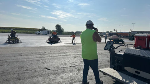
Crew & Equipment (Rules of Thumb)
Standard crew composition:
- 1 lead applicator (handles spray equipment, oversees installation)
- 2 prep/detail workers (surface prep, joint chasing, fabric placement)
- 1 QC/documentation person (testing, logging, photos)
Joint preparation tools:
- Concrete sawcut or routing equipment
- Industrial vacuum for dust removal
- Solvent-wipe materials and applicators
- Fabric cutting tools and measuring equipment
Application equipment:
- Plural-component spray rig for elastomeric topcoats
- Hand tools for detail work at joints (rollers, brushes, squeegees)
- Mixing equipment for primers and surfacers
QC instruments:
- Dry film thickness gauge (ultrasonic or destructive)
- Pull-off adhesion dolly kit with recording adhesion tester
- Holiday detector (spark tester or wet sponge setup per coating thickness)
- Environmental monitoring: thermometer, hygrometer, dew point meter
Timeline impact: Add 1-2 days per 100 linear feet of joints compared to a conventional coat-over approach. For a typical municipal basin with 400 linear feet of joints, budget an extra week for proper joint-integrated installation.
Materials (Generic Specifications)
Primer: Two-component epoxy system with good wetting and penetration characteristics. For projects with moisture concerns or accelerated schedules, specify moisture vapor barrier (MVB) qualified primers tested per ASTM F3010.
Reinforcement fabrics:
- Geotextile for higher-movement joints and corners — compliant, flexible, forgiving of field conditions
- Fiberglass mat or woven roving for moderate-movement joints — higher tensile and tear capacity, stiffer structural response
Wet-out resin: Epoxy or polyurethane compatible with the overall system and service environment. Must provide excellent fabric saturation and encapsulation.
Surfacer: Low-porosity epoxy surfacer that minimizes pinholes and provides a sound base for spark testing. Should feather smoothly without creating ridges.
Elastomeric topcoat: Polyurea or polyurethane lining with adequate elongation (minimum 300% for polyurea), tear resistance, and chemical/temperature suitability for the application.
For potable water contact, verify products are listed to NSF/ANSI/CAN 61 at the intended surface area-to-volume ratio for your specific tank dimensions. Don't assume "NSF 61 listed" means it works at any thickness or tank size — check the actual listing parameters.
Where to Use Joint-Integrated Details (Decision Framework)
High movement or settlement risk:
- Structures on expansive soils where you've documented foundation movement
- Seismic zones with significant ground displacement potential
- Extreme climate zones with large daily or seasonal temperature swings (desert installations, northern climates)
- Sites with high water tables causing uplift pressure or where you've seen hydrostatic loading issues
Critical service applications:
- Potable water storage: Where coating failure creates public health concerns and regulatory compliance nightmares. Think about explaining to the water authority why you didn't use proven joint protection.
- Wastewater facilities: Where a 24-hour emergency shutdown for joint repairs costs $50,000+ in operational losses, bypass pumping, and regulatory fines.
- Secondary containment: Hazardous material storage where joint leaks trigger environmental liability and cleanup costs.
Long design life requirements:
- Owner specifications calling for 20-50 years between major recoating cycles
- New construction projects where getting it right the first time is more cost-effective than repeated repairs
- Critical infrastructure assets where long-term durability is mandated
Proven failure history:
- Rehabilitation of structures where you've already made two or three joint repair calls
- Replacement of conventional monolithic systems that failed at joints within 5-7 years
- Anywhere you've seen the pattern: coating looks fine, but joints are leaking
Payoff: Expect an upfront labor premium of approximately 15-30 percent for joint chasing, reinforcement installation, and surfacer application compared to a conventional coat-over approach. However, you'll see substantially fewer warranty callbacks, longer service intervals, and dramatically reduced owner complaints. The math works: spend an extra $15,000 on proper joint details now versus $60,000 in emergency repairs, equipment mobilization, and reputation damage three years from now.
Real-World Case Studies (Anonymized)
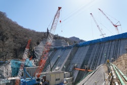
Municipal Wastewater Basin (~7.5 Million Gallons)
Project scope: Activated sludge basin with documented joint movement from thermal cycling and biological loading
Crew: 4 workers over 12 days including joint preparation and system installation
Challenges: Working around active biological processes, H2S exposure requiring respiratory protection, odor management, and maintaining treatment operations during coating work
Results: After 11 years of continuous immersion with pH swings from 5.8 to 8.2, reinforced joint zones show zero delamination or cracking. Adjacent areas with legacy monolithic coating (installed 3 years earlier on a different section) required $45,000 in patch repairs at year 4 and complete replacement at year 8.
Contractor note: Owner now specifies joint-integrated details as standard for all new basin work and rehabilitation projects.
Potable Water Reservoir (~12 Million Gallons)
Project scope: Reinforced concrete reservoir on soft clay foundation with documented differential settlement between wall sections
Crew: 5 workers over 18 days including extensive joint preparation at construction joints and wall-to-slab transitions
Challenges: Meeting stringent NSF 61 requirements for potable water contact, coordinating with water utility shutdown schedules, achieving proper surface profile on damp concrete in spring conditions
Results: Seven years post-installation, coating system maintains full NSF 61 compliance and structural integrity despite measured differential settlement of 2.3 inches between adjacent wall pours. Hydrostatic testing at full capacity shows no leakage at joints.
Contractor note: Structure passed 5-year regulatory inspection without findings. Comparable reservoir built same year with conventional monolithic coating showed joint leakage at 4-year inspection requiring $120,000 in repairs and re-lining.
Fire Water Tank (~500,000 Gallons, Rooftop Installation)
Project scope: Steel-reinforced concrete fire suppression tank exposed to extreme temperature cycling in desert climate
Crew: 3 workers over 8 days on a fast-track schedule
Challenges: Roof access logistics, extreme surface temperatures (ambient 110°F, substrate 140°F+), wind exposure affecting spray application, working around active fire suppression system
Results: Nine years of continuous service through temperature swings from 15° F (occasional winter lows) to 115° F+ (summer highs) without joint failure, delamination, or loss of water-tightness.
Contractor note: Comparable fire water tank at sister facility, built same year with conventional coating specification, experienced joint failures at year 3 requiring emergency repairs during fire marshal inspection. Facility now specifies joint-integrated approach for all elevated water storage.
Troubleshooting Guide (Field Problem-Solving)
Problem: Pinholes appearing at reinforcement edges
Cause: Under-wetted fabric leaving dry spots, or porous surfacer application
Fix: Abrade affected area to rough profile → Solvent wipe to remove dust → Re-prime if base coat is compromised → Apply additional surfacer → Reapply topcoat → Retest with holiday detector
Prevention: Ensure complete fabric saturation during installation; verify wet-out by visual inspection and hand-feel before surfacer application
Problem: Edge shear or cracking at joint interface
Cause: Joint movement exceeded design capacity; insufficient reinforcement width or weight; inadequate anchorage in chase
Fix: Remove failed section → Increase reinforcement width (12-18 in. each side vs. original 6-12 in.) → Upgrade to heavier fabric weight or double-layer application → Verify topcoat strain capacity is adequate → Reinstall system
Prevention: Accurately assess expected movement during planning phase; when in doubt, overdesign the joint detail rather than undersize it
Problem: Blistering or delamination in joint areas
Cause: Moisture vapor drive from concrete, or contamination (salts, oils, residues) not removed during surface prep
Fix: Remove blistered coating → Verify concrete moisture with ASTM F2170 and MVER testing → Test for soluble salts if suspected → Implement proper drying or mitigation → Use MVB-qualified primer system → Reinstall coating
Prevention: Always perform moisture testing before coating application; don't skip this step even on "dry-looking" concrete. Clean thoroughly and test for contaminants on rehab projects.
This article presents standards-based methodology and vendor-neutral guidance applicable to any compatible coating system. Additional field checklists, technical diagrams, or case study details available upon request.
This article is intended for educational purposes and represents current industry best practices. Contractors should consult with qualified engineers, coating manufacturers, and relevant building codes for project-specific requirements and specifications.