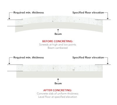
Cast-in-place reinforced concrete structural members deflect under load. This deflection can become a problem when it reduces the opening that a prefabricated manufactured item is to fit, causes water ponding on roof slabs, requires excessive self-leveling fill to accommodate flooring, or when deflection is visible to owners, or occupants of a structure.1 Whatever the cause of the problem, engineers have sometimes tried to control deflection effects by requiring cambered form soffits. Typically, the amount of camber is set in hopes of matching deflection values estimated on the basis of concrete dead weight (Fig. 1). Formwork camber requirements for cast-in-place reinforced concrete are far less common today than in the past, but when bidding a job that requires forms to be cambered, concrete contractors should be cautious. According to ACI’s Formwork for Concrete, contractors are expected to “…set and maintain forms so as to ensure completed work to the camber specified by the engineer/architect, within the tolerance limits specified" 2 [emphasis added]. ACI 117 does not have a tolerance on camber and setting reasonable tolerance limits is not an easy task for the engineer/architect as is discussed later.
A Deflection Calculation is Just an Estimate
The calculated deflection on which camber is based is not very reliable. The best estimate of deflection for reinforced concrete members is probably accurate to no more than ± 25%.3 Thus, if 2 in. of deflection were estimated, that actual deflection could range from 1½ in. to 2½ in. and a resulting slab of uniform thickness could have an unacceptable built-in ½-in. hump or sag after shores are removed.. Deflection calculations are needed for camber planning purposes, but are the resulting deflection estimates any good?
Camber tolerances need to be assigned to the formwork and measured prior to placing concrete. If a camber tolerance is applied to the deflected concrete member, the inaccuracy of the deflection will swallow the camber tolerance. On multi-story projects that require camber, the camber is initially estimated by the engineer and then measured during construction of the first few bays or floors, and adjusted as needed. The engineer and contractor work together to resolve the issue.
Applying the Steel Approach to Concrete
Based on a review of past and current research, the Steel Solutions Center produced guidelines for specifying camber.4 The authors also acknowledged that: “Though there are times when specifying beam camber can be advantageous, there are situations in which it is also impractical.” That’s good advice for cast-in-place concrete construction as well. The steel camber guidelines are provided with our recommendations for the corresponding concrete camber:
- Don’t specify camber less than ¾ in. on steel beams. The rationale is that camber losses would make this small amount ineffective. In contrast, for cast-in-place concrete, the ACI 117 elevation tolerance of ± ¾ inch would dwarf any small camber. A prominent structural engineer suggests a minimum camber of about 1 in. to avoid trivial measurements that are difficult to control in the field.1
Specify camber in ¼ in. increments on contract documents. Based on the suggested 1-in. minimum camber for concrete mentioned above, concrete camber increments should not be specified at less than ¼ in.- Don’t specify camber for steel beams less than 24 ft. Similar to steel beams, short reinforced beams will not deflect much and camber is not needed if the designer uses ACI 318 depth-to-span ratios to control deflection. Consider camber on reinforced concrete beams longer than 24 ft.
- In most cases, do not camber spandrel beams because cladding system connections are difficult to coordinate. This is also applicable to cast-in-place concrete where embeds would have to be placed more precisely than for non-cambered spandrel beams.
The guidelines also discuss how much load should be assumed in determining camber. Because engineers tend to be conservative, and thus overestimate loads, beams to be cambered require a dead-load estimate that emphasizes accuracy.
Stepping outside the steel approach, designers can require post-tensioned concrete slabs and beams which controls deflection and eliminates the need for camber under most owner applications.
Camber Costs
Forming costs reflect the difficulty of forming and clarity of engineers’ instructions for camber. Specifics of the forming system to be used on a project are left up to the contractor. But if instructions for camber in the bid documents are vague, there is often little time during the bidding process for the contractor to clarify the designer’s intent. A good estimator will take this into account by increasing the bid price. Booker5 cited the following specification requirement as an example of this:
“Induce camber of 1/8-in. per 10 ft of span plus ¼ in. for beams, and 1/8-in. per 10 ft of span plus 1/8 in. for slabs other than two-way slabs. For two-way slabs, camber the center of the longer centerline the sum of the camber based on 1/8-in. in 10 ft of spans in both directions; form the intersection of the camber slope at a 45 degree angle in plan for the slab corners.”
He states that cambering two-way slabs in both directions is costly because it involves a network of hips and valleys running diagonally to each other. Steep soffit slopes created by such cambers require forming members to be cut at the grade breaks. This wastes material and decreases labor productivity because sizes of the forming materials can’t be standardized. He says it will always be less expensive, faster, and less wasteful of forming materials to camber the slab forms in only one direction.
Camber Tolerances?
The ACI tolerance specification (ACI 117-15) is silent on tolerances for camber. That may be because so many variables affect the outcome of cambering forms. As mentioned earlier, load estimates may be unduly conservative (high). Some of the settlement may also be caused by deflection of the forms due to closure of form joints, settlement of mudsills, and columnar shortening of forms after the concrete is placed.2 Early-age concrete strength gain and the potential for cracking when shores are removed must also be considered.
A mandatory checklist item could be added to ACI 117-15, requiring the designer to specify camber tolerances in any design documents that require camber. As an added aid to the contractor, Booker suggests that the designer specifically locate the amount of camber on the floor plan drawing where required. Although this is not related to tolerances, it removes “intent” from the contractor and places design responsibility where it belongs.5
There is currently a discussion among ACI Committee 117 as to whether or not a camber tolerance should be added to ACI. Based on an informal poll of ASCC Technical Committee members, camber has not been commonly specified on their cast-in-place concrete projects. We would be interested in a larger sampling based on responses of Concrete Contractor readers. If you have bid on or built jobs with specified camber of concrete members within the past 10 years, please contact either of us at the emails given and give us a brief description of the camber requirements.
References
1. Fling, Russell S., Practical Design of Reinforced Concrete, John Wiley & Sons, 1987, p. 241.
2. Johnston, David W., Formwork for Concrete, ACI SP-4, 8th ed., American Concrete Institute, 2014, pp. 8-10 through 8-13.
3. Suprenant, Bruce A., “Construction of Elevated Concrete Slabs,” Concrete Construction, Nov. 1990, pp. 910-920.
4. Downey, Erika Winters, “Specifying Camber,” Modern Steel Construction, July 2006, 3 pp.
5. Booker, Denver, “Cambering of Soffit Forms,” Concrete International, Nov. 1994, pp. 35-36.