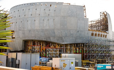
Imagine building a structural concrete sphere one hundred fifty feet in diameter weighing 25 million pounds (25,000 kips) held in position twelve feet off the ground by four concrete columns with seismic isolators between the columns and the sphere. A building with no structural connection to the columns or the ground, the sphere can move freely approximately 30 inches horizontally during an earthquake. Then imagine the structure is being built on tar-sand, with bedrock being nowhere to be found—not an ideal ground condition. The sphere is part of a new theater and museum complex being built for the Academy Museum of Motion Pictures in Los Angeles (LA) and it is the result of a close collaborative effort between contractors, engineers, architects, consultants and material suppliers.
The sphere will house a 1,000 seat theater and rooftop terrace. It will be connected to an adjacent building housing the museum’s exhibition spaces, an education studio, a conservation studio, a 288-seat theater, a retail space, and a restaurant and café. Academy Museum’s is located next to the LA County Museum of Art (LACMA), The La Brea Tar Pits & Museum, and several other museums in the LA Miracle Mile neighborhood along Wilshire Blvd. Kerry Brougher, Director of the Academy’s museum says the dream of having a museum for the film industry started in 1929, early in the industry’s life. But nothing happened and the idea was discussed again in 2008, just before the country’s recession/depression. Talk started again in 2012 when an iconic Streamline Moderne historic May Company department store building became available and a fundraising efforts began to fund the project.
The project includes a complete rehabilitation of the former May Co. building, now called the Saban Building, plus the construction of the spherical structure. Both the rehab and the new theater construction are challenging but it’s the sphere that is pushing the edges of technology.
Design and engineering
Enzo Piano Building Workshop, Genoa, Italy, an architect known for designing world-class museums, is the designer of the museum’s campus and Gensler, Los Angeles, is the executive architect on the project. BuroHappold Engineering, Los Angeles, Calif., is the structural engineer of record. Derrick Roorda, a principal of the company and leader of their structural group in LA, says he got involved with the project in 2013 as the structural and design control engineer. He defines the engineering challenges:
- Only four points of the structure touch the ground
- The structure must insulate noise from the outside
- Any single element of the structure influences the whole, everything must work together
- Preventing the sphere from being destroyed in an earthquake, it must to be able to move horizontally as much as 30-inches
- The three bridges between the theater and the museum building must allow for movement
- The architect wanted precast concrete on the outside of the sphere—a more controlled concrete appearance
- Complete support of the sphere during construction so there wouldn’t be any movement.
Roorda worked in close collaboration with Morley Construction Co., Santa Monica, Calif., the engineers from the Peri Formwork Systems Inc., Irvine, Calif., and with a consultant engineer, KCJ Engineering, Laguna Hills, Calif., hired by Morley.
Academy Museum COO Rich Cherry says the first phase of the construction was awarded to the joint venture of Morley+Taslimi and the second phase construction was awarded to Matt Construction based in Santa Fe Springs, Calif. But for both phases of the project Morley was retained to perform the structural and architectural concrete work.
Preparing for the construction
Bob Stephens, Morley’s Project Executive, says it was clear from the start that the sphere must be fully supported during construction. Stephens explains the problem this way. “It’s like holding a ping pong ball,” he says. “If you squeeze it in your hand it’s crush resistant but if you cut a round hole in the ball it crushes easily and loses its shape. A sphere isn’t structurally sound unless it is complete” So Morley met with Mark Harrison, a PERI Sales Engineer, and Tim Cruz, the sales manager for the US South West Region of PERI and their engineering team to discuss the problem. PERI’s engineering group from their headquarters in Germany also got involved. Cruz said they recognized the project as very special, one they probably wouldn’t encounter again and they liked the challenge. Here were some of their thoughts:
- Support would be needed during the whole construction period. Typically support is removed after concrete reaches its design strength
- Morley’s engineer located 133 load points on the structure that required special shoring. Monitoring would be required and adjusted when necessary
- A range of shoring towers would be needed to keep costs down and the different systems would have to work together
- Close collaboration between themselves, the structural engineers, and Morley would be needed throughout the entire construction period
PERI recommended four of their shoring systems for the project:
- VST Shoring Towers, a four or six-leg system with each leg able to support 180,000 pounds of load (they are colored orange and green in the photos).
- HD 200 shores, a system clustered in groups of four legged tower system capable of supporting 45,000 pounds per leg (white triangular colored legs in photos)
- MULTIPROP shoring system, a system clustered in groups of four tower system able to support 18,000 pounds per leg (yellow and silver legs in photos)
- PERI UP Flex Shoring able to support 8,400 pounds per leg (silver legs in photos)
From the bottom up
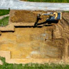
The wall of the Saban building facing the sphere was removed along with its basement floor. Stephens says piles (caissons) were installed under the building to add support. The area between the Saban building and the sphere was excavated to build an underground 34-foot tall theater seating 288 people, an electrical vault, and an underground tunnel to bring mechanicals to the spherical Geffen Theater above, along with other back-of-house spaces. Stephens says the excavated soil was tar sand so they used sensor equipment, commonly referred to as “sniffers” to warn workers of noxious gases in excavated areas. They also installed a methane barrier beneath all underground rooms, tunnels, and plinths (columns). The membranes were sandwiched between concrete slabs for protection and the barriers are installed so that gas can move around the membrane and exit away from the buildings.
Piles and plinths. There are four plinths under the sphere with 43 augercast 24-inch diameter friction piles installed under each double set of plinths, The auger drilled 90 foot deep holes and it was pulled up without rotating the drill. As it was lifted concrete was pumped through the center of the bit to fill the hole. This method provides maximum friction between the concrete and the side of the hole. Two 500 cubic yard pile caps on top of the piles distributed the load evenly. These elements all required mass concrete mixes. Eric DeCrescenzo, Sales Representative for Catalina Pacific Concrete (a Division of CALPORTLAND Co, Glendora, Calif.), Azusa, California says they supplied all the mass concrete for the job. “The strength requirement was 7,000 psi in 56 days. We used a glacial-formed hard aggregate referred to as “Orcha Aggregate” to increase strength and reduce the amount of cement to reduce the heat of hydration.” The hydrating concrete couldn’t exceed 160ºF and there couldn’t be more than a 35ºF difference between the center and the edge of placements.
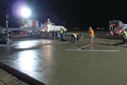
Transfer girders. There are two highly reinforced transfer beams placed on top of the plinths. They carry the entire weight of the theater and transfer it to the plinths. Each beam is 12 to 14 feet wide, 10-feet tall and 132 feet long. The beams form part of the belly of the sphere so their ends are spherically curved to match the curve of the sphere at each end. Stephens says the 1330 cubic yards of mass concrete for the girders had the same requirements as the plinths. DeCrescenzo says Catalina added as much as 1,100 lbs of ice per load during batching to deliver concrete at approximately 60 F. Upon further analysis the allowable maximum temperature of hydration was raised to 170 F by the CTL Group, Morley’s consulting engineer on mass concrete issues and heat of hydration. They started the placement at 11:30 pm on a Friday night when aggregate piles at the ready-mix plant were coolest and continued until 11:00 am the next day. Afterwards the beams were enclosed in insulation to keep the temperature spread within the beams to less than 35ºF.
Belly Slabs. There are approximately 14,000 square feet of belly slabs and transfer girder surface at the bottom of the sphere. The belly slab between the transfer girder and the Sabon building is 12-inches thick and flat. But the 18-inch thick slab on the other side of the transit girders sloped at a 15 degree angle with the “wing slabs” on either side of being 39 degrees—too much angle to keep ready-mix concrete in place. So Morley placed ready-mix concrete where they could and at the same time had Superior Gunite, Lakeview Terrace, Calif. shoot three-inch slump shotcrete in the high-slope areas.
Seismic isolators. They are one of the great technical advancements for concrete structures in seismic areas. Victor Zayas, president of Earthquake Protection Systems Inc., Vallejo, California, says “seismic codes reduce the risk of structure collapse but allow substantial damage, but seismic isolators can minimize damage sufficiently to retain facility functionality, a world of difference in performance objective.” By allowing the earth to move in an earthquake while a structure remains relatively still, money is be saved on the structure and foundation costs and the structures receive little damage in an earthquake. Eight isolators are installed on this project; two on top of each plinth. To describe how they work Zayes says “with these isolators the structure responds to earthquakes with a gentle pendulum motion, instead of violent horizontal shaking. Concrete structures can now function after the most severe earthquake.”
Zayas adds “the 1971 San Fernando earthquake caused the collapse of concrete structures, resulting in a UC Berkeley study that included my PhD work to develop steel structures that could suffer severe damage during earthquakes but not collapse. However concrete structures with seismic isolators cost less to build and suffer far less damage than the typical code compliant steel structure. Using seismic isolators that deliver post-earthquake functionality, as required by ASCE 7-16 for essential facilities, California can return to building most buildings in concrete.” Stephens says each isolator for this project is approximately 7 feet in diameter and weighs 28,000 pounds.
Constructing the sphere
The shoring systems described above were installed under the transfer girders and belly slabs for the sphere to reduce up and down movement during construction. The engineering team located points where shoring towers were needed to carry the majority of the load—the plinths don’t carry their full design load during construction. Morley placed engineered concrete six-inch thick slabs on grade with thickened areas up to two feet, to support the up to 20,000 pound shoring towers, moved into place with a tower cranes. The shore towers fully support the weight of the sphere, starting with the construction of the girders and belly slabs and continuing after the ring beam is completed at the top of the structure. Morley surveys points on the structure at regular intervals to check for any signs of movement.
Mark Hildebrand, President of Willis Construction, San Juan Bautista, Calif., says this project is a very unusual one for them. “Usually we get involved after the structure is in place but on this project our precast panels serve as permanent architectural formwork for the structural concrete.” The architect wanted the sphere to look like concrete but he wanted it to have the fine finish that precast concrete can provide.
Hildebrand said they created a digital model of the outside shape and used a Computer Numerically Controlled (CNC) router to cut the positive shapes in foam. Using this they cast forms for the panels with Glass Fiber Reinforced Concrete (GFRC). All the precast panels for the job are cast on these forms with special attention paid to the panel edges in order to provide crisp lines on the outside of the sphere. The panels are four inches thick with 4x4-4x4 welded wire fabric reinforcement cast with 7,000 psi concrete. Willis digital model included all the penetrations in panels for attaching the glass canopy to the top of the structure to ensure their proper location on the face of the sphere. Installing the panels on the jobsite is also part of their contract.
Greg Wade, the Vice President of Matt Construction, Santa Fe Springs, Calif., the general contractor for phase 2 of this project, says that elaborate interior steel frame supports were built into the sphere to provide a perfect spherical shape to attach the precast panels to. “These frames also support the structure. After shotcrete is installed the parts of the frame protruding from the shotcrete is removed.”
The structural concrete for the sphere walls is shotcrete. With the precast panels(with a bond-breaker on the back side of the panels) serving as a form, a two foot thickness of shotcrete is sprayed against the panels through heavy steel reinforcement and finished on the inside to mirror the spherical shape of the outside. This concrete is also specified to be 7,000 psi. Stephens says the nozzle-man must be certified by the City of Los Angeles for the project and then is the only one permitted to spray concrete on the job. As he works he is followed by a worker with a blow pipe to keep rebar clean and to help remove excess material.
Installing the ring beam
Near the top of the precast panels a ring beam going all around the sphere will be installed and covered with concrete, it will tie the structure together and finally give the sphere rigidity. This makes it possible to finally remove all the shoring towers—the plinths supporting the sphere for the first time. A concrete deck will also be installed above the ring beam. The approximate 10,000 square foot floor will be used for special events. It will be covered by a glass canopy positioned 2 feet away from the precast and supported entirely by steel imbeds going through the precast walls. Aside from rain cover this space will be open to ambient conditions.
BIM
Projects like this would be very difficult to build, if not impossible, without Building Information Modeling (BIM), a 3D Digital model with a data base providing useful information for all contractors. Typically started by the architect on software such as Revit by Autodesk, contractors and engineers add their own information to the model. Checking for conflicts (clash detection) by the general contractor makes it possible to locate most areas of conflict before fabrication starts. But the development of BIM models continues throughout a project, finally being used to create as-built drawings.
Matt Construction manages the BIM coordination for the job and provides clash detection. Their sub-contractors work with these models to develop their own BIM drawings to help coordinate the work. Ed So, the Senior Virtual Construction Manager for Morley (an architect by education), works full time managing and creating BIM on this job. He says he generates layout points for their work, material quantities, takeoffs, schedules, sequence diagrams, coordination drawings for constructability, and uses it to help monitor their point load towers for movement. He also uses 3D printed plastic models showing job details to help discussion in team meetings and for workers to visualize what they are being asked to build. “Sometimes even a 3D drawing is too hard to visualize,” he says.
Closing thoughts
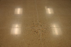
The line between decorative concrete and architectural concrete is becoming more blurred as buildings like this one come into being. The design features the natural color of concrete and the high-quality forming and concrete placements draw people into the project, causing a natural curiosity about what the inside looks like.
Just about everything in this project poses challenges requiring cutting edge technology to solve. Both the Matt and Morley companies thrive on this kind of work. But the challenges are personal too. Stephens says jobs like this make it exciting to go to work in the morning—one knows they are doing something special. He thrives on the teamwork and the technical demands of a project like this and he looks forward to the day when he can proudly show the theater to his grandchildren, telling them “We did this—we were here.”