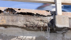
Concrete contractors are still being penalized when welded wire reinforcement (WWR) is found to be incorrectly positioned in concrete slabs. We just heard of an interior topping slab for which structural drawings required reinforcement with 6 x 6 – W2.9 x W2.9 WWR but the drawings did not call out a specific positioning in the cross-section of the 5-in.-thick topping. Instead the drawings only called out a 2-in. concrete cover for all reinforcement. The general contractor measured the WWR location after concrete placement, said it did not provide 2 in. of cover, then removed it. It is unclear who will replace the topping and where the WWR will be positioned in the replaced topping, but it is clear that the general contractor will back-charge the concrete contractor.
The dilemma: Engineers specify positioning of a reinforcement product that will almost always move out of position during construction, and suppliers profit from selling a product they promoted. But contractors pay for removal and replacement when it’s discovered that the product is in the wrong position. This cycle needs to stop. We present the following information from several industry documents in hopes that the cycle can be broken.
Industry Documents
ACI 117 Specifications for Tolerances for Concrete Construction and Materials:1 Starting with the 1990 edition, ACI 117 indicated that it was a Mandatory Specification Checklist requirement for the Architect/Engineer to specify tolerances for WWR as ACI 117 did not include these tolerances. This is still true in the most recent revision of ACI 117 reapproved in 2015. As a member of the committee, I felt we did not have enough information to make a tolerance statement on WWR.
ASCC Position Statement #2 Location of Rolled Welded-Wire Fabric in Concrete:2 Published in ACI’s Concrete International in February 2003, this statement reminded specifiers that ACI 117 did not have tolerances on WWR, and that concrete contractors can’t place WWR so it will stay in position. The document also indicated that supporting WWR properly would significantly increase the cost. At that time, ASCC recommended using sheets of WWR with wire spacings of 12 inch to allow for construction foot traffic.
 Table 1: Suggested Support Spacing for WWR from the Wire Reinforcement Institute
WRI Recommended Support Spacing for WWR:3 In the 2008 document, WRI suggested the support spacing for WWR shown in Table 1. However, they also provided a caveat stating “the applicability of the suggested support spacings in Table 1 may best be confirmed by conducting on-site testing of the proposed arrangement of supports”. WRI repeated these suggested support spacings in a 2016 document4 and added “The various codes and standards do not give advice on spacing of supports for WWR. The WRI Tech Fact, TF 702 R2 does have guidelines for support spacings (shown in Table 1) based on many years of experience.” WRI does not cite any references to support the spacing guidelines.
ACI 301 Specifications for Structural Concrete:5 Section 3.2.5 of ACI 301-16, “Specifications for Structural Concrete,” addressed WWR positioning, and the requirements are likely to be cited in many specifications. Table 2 summarizes the requirements, which are divided into two groups:
- Group A applies to WWR in slabs on composite deck and slabs-on-ground.
- Group B applies to WWR in elevated formed slabs, slabs on noncomposite steel deck, and members not covered in Group A.
 Table 2: WWR Positioning Requirements in ACI 306-16 "Specifications for Structural Concrete"
As can be seen in Table 2, ACI 301-16 doesn’t specify a tolerance for Group A wire sizes 4.0 or greater. Section 3.3.2.5 simply says: “Place reinforcement as indicated in contract documents.” For wire sizes less than 4.0, a maximum support spacing of 12 in. is required.
For Group B, when using wire sizes W4.0 or D4.0 or larger, the WWR must be placed and supported “…before concrete placement to maintain location within tolerances indicated for nonprestressed reinforcement in ACI 117.” ACI 117-10(15) specifies a ± ¼ in. tolerance for slabs with thicknesses of 4 in. or less, and a ± 3/8 in. placement tolerance for slab thicknesses between 4 and 12 in. Thus the placement tolerance of WWR for Group B for large wire sizes is the same as that for reinforcing bars. For wire sizes W4.0 or D4.0 or smaller, the 12-in. maximum support spacing is again required.
Section 3.3.2.5 of ACI 301-16 also require the contractor to “Support welded wire reinforcement in accordance with CRSI RB4.16 to maintain positioning during concrete placement.” However, RB4.1 is a product standard for reinforcing bar supports and does not cover WWR positioning.
 Table 3: Measured Location of WWR on Three Projects
Industry Measurements of WWR Location
In a project funded by the Wire Reinforcement Institute (WRI), a total of 122 measurements of WWR locations were taken using a concrete covermeter on three different projects.7 Note that the wire sizes are large, ranging from 6.0 to 8.6. The measured average cover and the calculated standard deviation of the data, along with the tolerances, are shown in Table 3. WRI reported the conclusion for each of these projects as: “This testing indicated that 95% or more of the WWR cover measurements were within compliance and the cover for the WWR was acceptable.”
It is important to note that this conclusion is only valid for all three projects if the tolerances are 2 to 3 inches, ± 1 to ± 1 ½ in. This is in stark contrast to the ACI 301 requirement for these wire sizes that would limit placement to ± ¼ or ± 3/8 inch.
In another study,8 sheets of welded-wire reinforcement were supported by 3 in. high slab bolster upper bar supports at varying spacings and held in place by 50 lb. bags of dry grout mixture. At each spacing, a man weighing 180 lb. stood in the center of the bar supports to simulate a construction worker walking across the area before concrete placement. With the man standing on both feet on the sheet, the distance from the base to the section of wire beneath his feet was measured.
 Table 4: Calculated Deflection Under a 180-lb. Weight for WWR Initially Positioned at 3-inch Cover
Table 4 shows the calculated deflection based on the starting positon of 3 inches and the measured distance from the base to the WWR with the man standing on it. For wire sizes of 4.0 and greater, the WRI-suggested support spacing in Table 1 would not allow placement compliance with ACI 301-16. In addition, the ACI 301 maximum support spacing of 1 ft. would result in deflections of 6 x 6 – W1.4 x W1.4 and 6 x 6 – W2.0 x W2.0 welded wire reinforcement that exceed ACI 117 tolerances.
This study did what WRI recommended, that the applicability of the suggested support spacings may best be confirmed by conducting on-site testing of the proposed arrangement of supports. This study shows that the suggested WRI support spacings do not work.
Integrating Industry Documents and Industry Measurements
Based on a review of the industry documents and measurements, we need to start over to find a solution other than remove-and-replace for positioning of WWR that doesn’t meet the current requirements in ACI 301-16. This is an industry issue that has plagued concrete contractors for decades. WRI indicated that the three projects in which WWR locations were measured were performing adequately with a tolerance of ± 1 in. or more. What we need is an understanding of which tolerance values will result in acceptable performance. Setting tolerance values for WWR at ± ¼ in. will continue the removal and replacement cycle.
References
1. ACI 117-10 (05) “Specification for Tolerances for Concrete Construction and Materials and Commentary,” American Concrete Institute, 2005.
2. ASCC Position Statement 2, “Location of Rolled Welded-Wire Fabric in Concrete”, Concrete International, February 2003.
3. “Supports Are Needed for Long-Term Performance of Welded Wire Reinforcement in Slabs-on-Grade,” Tech Facts TF 702-R-08, Wire Reinforcement Institute, 2008.
4. “Structural Welded Wire Reinforcement”, Manual of Standard Practice, 2016.
5. ACI 301-16, “Specifications for Structural Concrete,” American Concrete Institute, 2016.
6. “Supports for Reinforcement Used in Concrete”, RB4.1-14, Concrete Reinforcing Steel Institute, 2016.
7. Snell, Luke M., “Cover of Welded Wire Fabric in Slabs and Pavement”, Concrete Construction, 1997. Also published as “Studies Show Properly Covered WWR Produces High Performance Concrete” by Wire Reinforcement Institute, CS 299-R-03, 2003.
8. Neuber, Joseph, “Support Requirements for Welded-Wire Reinforcement in Slabs”, Concrete International, American Concrete Institute, September 2006.









![Strux Macrofibers 58c9b97fd4aaf[1]](https://img.forconstructionpros.com/mindful/acbm/workspaces/default/uploads/2025/08/strux-macrofibers58c9b97fd4aaf1.cNEEIfY9kp.png?ar=16%3A9&auto=format%2Ccompress&fit=crop&h=135&q=70&w=240)
