Scaling is one of the most common causes of disputes between contractors and owners regarding pavements, curbs and gutters, sidewalks, and other concrete construction elements that are exposed to freeze-thaw conditions. In many cases scaling is cosmetic and surficial in nature. In other cases it may be a precursor to significant damage that requires removal and replacement.
Scaling mechanisms in concrete
The American Concrete Institute (ACI) defines scaling as “local flaking or peeling away of the near-surface portion of hardened concrete or mortar."[1] Scaling may occur in desert environments as a consequence of salt weathering, but this discussion focuses on the several different types of scaling mechanisms that occur in freeze-thaw environments. The typical consequences of scaling associated with frost damage include changes in the appearance and smoothness of the wear surface. In severe cases the loss of cover over reinforcing steel is also an issue. The ACI Guide to Durable Concrete [2] provides valuable information not only on mechanisms associated with frost damage, but aspects of design and construction practices (e.g., transporting, placing, finishing and curing) that can minimize the potential for frost damage in general and scaling in particular.
The most common scaling mechanisms are:
- Classic freeze-thaw scaling, where sub-horizontal micro-cracks leads to loss of material by flaking.
- Micro-delaminations, where very thin layers of mortar detach in coherent sheets from the top surface.
- Mortar flaking, which involves the loss of mortar over coarse aggregate particles.
These mechanisms are not mutually exclusive and sometimes all of them can occur on a given job. The following sections describe what petrographers may see when these mechanisms occur.
Classic freeze-thaw scaling
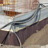
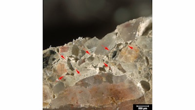
Here we define classic freeze-thaw scaling as the loss of material from a surface due to the development of short, discontinuous micro-cracks subjacent to or just below the scaled surface (Figure 1). In most cases these micro-cracks are limited to the top 1-3 mm (40-120 mil) of the concrete. The micro-cracks are sub-parallel to the scaled surface (sub-horizontal in pavements and sidewalks) and tend to wrap around aggregate particles. The micro-cracks may or may not be free of secondary deposits.
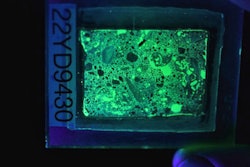
A concrete mixture that is designed properly for scaling resistance has a low amount of freezable water, durable aggregates, and a proper air void system. All of these factors work to diminish internal stresses when freezing occurs. Hard aggregates with low absorption are usually durable in freeze-thaw environments. In general, a low water-cementitious materials ratio (w/cm) that is less than 0.45 is adequate for reducing the freezable water content. A petrographic examination per ASTM C856 [3] allows petrographers to assess whether a mixture satisfies these criteria. Petrographers use ASTM C457 [4] to determine the properties of the hardened air void system in concrete. Frost resistance comes not only from having the proper air content (generally 6 ± 1.5% air), but having the right size (specific surface) and spacing of the voids (spacing factor; Figure 2). In the field, total air content is measured most commonly by the volumetric method [5] or the pressure method.[6] However, these methods don’t measure specific surface or spacing factor, so a load of concrete may pass field standard measurements for air content in the field but still have inadequate air void systems. We will discuss the details of the air void system and differences in field measurements of fresh concrete compared to laboratory measurements of hardened concrete in a later article. If the concrete is lacking proper proportioning, the scaling observed today may be a precursor to more significant freeze-thaw damage later.
Micro-delaminations
This scaling mechanism involves the loss of thin sheets of mortar from the top surface, rather than progressive flaking of material (Figure 3). It occurs most commonly when inappropriate finishing practices such as a steel trowel are used on air-entrained concrete; occasionally poor curing may lead this type of scaling as well. The troweling depletes the air content of the upper-most layer of concrete, resulting in a material that lacks air entrainment in exactly the place where it needs it the most. As a result, sub-horizontal cracks develop subjacent to the finished surface. These micro-cracks cut around aggregate particles and are often free of secondary deposits. This type of distress is limited to the upper skin of the concrete.
Mortar flaking
This scaling mechanism involves the loss of mortar over coarse aggregate particles that are just below the finished surface (Figure 4). In the field, this type of scaling appears as isolated patches of lost mortar that expose the surface of the coarse aggregate particles. Mortar flaking occurs as a consequence of poor consolidation techniques and poor curing. When coarse aggregate particles are not sufficiently depressed below the finished surface, they tend to block the rise of bleed water to the mortar above them. Unless very diligent curing practices are followed, this results in poor cement hydration. Consequently, the mortar above the coarse aggregate particle is weaker and often more porous than the surrounding mortar and the strength of the paste-aggregate bond is diminished. As with micro-delaminations, the flaws associated with mortar flaking occur near the top surface of the slab, which is right where the quality of the concrete needs to be highest.
Deicer salts
It has long been known that deicers can accelerate scaling distress (see ACI 201.2R). Petrographers can evaluate if concrete has been exposed to deicers by taking slices from the top and middle of a core and using a laboratory method such as ASTM C1152 [7] to determine their chloride content. Concrete exposed to chloride-based deicers will have much higher chloride contents at the top of the core compared to the background level indicated by the middle slide. In recent years concern has grown regarding the effects of newer products that are used more and more widely for deicing and anti-icing. In general, more severe distress has been observed in new concrete and in many cases older concrete that had performed well for years has scaled significantly with the application of these newer products. We will discuss deicers in more detail in a future article.
Other factors
Other aspects of a job, such as drainage, can be critical factors in scaling as well. Inadequate drainage can lead to scaling in concrete that is properly proportioned, placed, finished and cured. The timing of a placement can also be crucial. Concrete exposed to freeze-thaw conditions before it is mature and relatively dry can lead to scaling, particularly if deicers are used on those first snow events. Providing petrographers with as much information as possible about these aspects of the job can be critical in understanding what scaling mechanisms are at play.
Conclusions
Scaling is a common form of freeze-thaw distress that involves the progressive loss of material from an exposed surface. It can occur from a number of different mechanisms that may reflect shortcomings in material properties, finish and/or curing as well as problems in drainage or maintenance practices. Petrographers can often recognize which mechanism(s) may underlie a scaled pavement using a combination of petrographic examination, air void analysis and chloride testing. By understanding the mechanism(s) that underlie surface scaling, it is often possible to determine sensible solutions to remediate these issues.
References
- Concrete Terminology, American Concrete Institute CT-13, http://www.concrete.org/Tools/ConcreteTerminology.aspx
- Guide to Durable Concrete, American Concrete Institute 201.2R-08, http://www.concrete.org/Publications/MCPOnline/MCPSearch.aspx?m=abstract&MCP_DocID=916
- Standard Practice for Petrographic Examination of Hardened Concrete, ASTM C856-14, Annual Book of Standards, vol. 4.02.
- Standard Test Method for Microscopical Determination of Parameters of the Air-Void System in Hardened Concrete, ASTM C457/C457M-12, Annual Book of Standards, vol. 4.02.
- Standard Test Method for Air Content of Freshly Mixed Concrete by the Volumetric Method, ASTM C173/C173M-14, Annual Book of Standards, vol. 4.02.
- Standard Test Method for Air Content of Freshly Mixed Concrete by the Pressure Method, ASTM C231/C231M-14m, Annual Book of Standards, vol. 4.02.
- Standard Test Method for Acid-Soluble Chloride in Mortar and Concrete, ASTM C1152/C1152M-04(2012)e1, Annual Book of Standards, vol. 4.02.