Each year the Concrete Foundations Association (CFA) based in Mt. Vernon, Iowa holds a contest to honor the best and most difficult foundation projects of the year. Over the years, contractors occasionally submitted projects that were complicated beyond one’s ability to foresee all the problems and therefore become financial losers. So Jim Baty, the executive director of the CFA, says they changed the rules of the competition so that submissions will reflect cutting edge technology but will also be profitable. “The quality of a project should not be based solely on its economic success but rather the quality of design and craftsmanship that go into it. A project that loses money is likely to be one that doesn’t stack up to such qualities,” he adds.
Most contractor members of the CFA build residential and commercial foundations that go only one story into the ground and those have been the most frequently awarded projects along with above grade concrete homes. But this year they voted to recognize a large commercial deep foundation with the grand prize award.
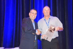
This also marks the first time a project application was submitted by the engineer of record for the job, and the first time the winner is a commercial project—not a residential one. The award winning project is the new Science Building for George Washington University in Washington D.C. and the engineering group is Ballinger, located in Philadelphia, Pennsylvania.
Articles appearing in the Concrete Contractor are usually told through the eyes of the contractor but this time you will have the opportunity to understand the challenges faced by the engineer and how his team addressed each challenge.
Building in Washington D.C.
In Washington D.C., if you want to build a tall building you don’t build up, you build “down”. That’s because of the “Height Act” enacted by Congress in 1899 and amended in 1910. It stipulates that commercial structures cannot exceed 130 feet in height (there are a few exceptions in designated areas) in order that government buildings and shrines won’t be eclipsed. So when George Washington University wanted to build a new science building they decided to build the first six stories underground. This included two floors with research labs having floor to floor heights of 16 feet and four floors of parking below that. The above grade eight floors plus a mechanical penthouse include research labs, classrooms, offices and visitor spaces. Edward Zinski, Associate Principal and Chief Structural Engineer for Ballinger, says his company specializes in this kind of work but the complexities of this substructure and its 74 foot deep excavation provided many unusual challenges for both his company and the contractor, Clark Construction.
Location challenges
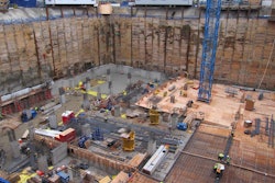
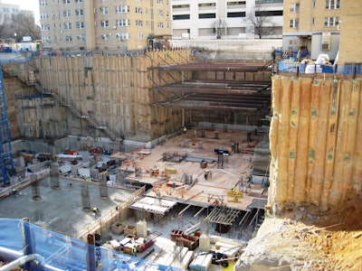
The new 700,000 square foot “Science and Engineering Hall”—with 300,000 square feet of the space being below grade—is located next to three dormitory buildings that were occupied during the entire time of construction. The shallow footings of these buildings at the edge of the excavation required deep underpinning. In addition, the Washington D.C. Metro tunnel was located within the adjacent street and care was taken to prevent damage to that structure.
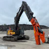
Rock elevations on the site varied from 35 feet to 74 feet so significant amounts had to be excavated and removed. Some of this was accomplished by blasting, completed while the surrounding buildings were occupied—students occupied the dorms, with times coordinated as to when the blasts occurred.
The depth of the foundation created other unique challenges. Zinski said they had to plan on lateral soil pressures as high as 3,500 pounds per square foot (psf) on the basement walls. They then had to extensively evaluate the substructure’s two-way concrete floors for enormous lateral buckling forces translating through the floor diaphragms, with sloping parking ramps and other discontinuities in the floors.
Protecting the hole and the surroundings
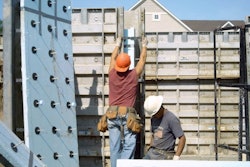
Holes this deep with surrounding buildings must be protected from collapse and several methods were employed by Clark Excavation to do that.
Zinski says near the existing dormitories they used “tangent piles”—drilled shafts filled with steel soldier piles, supported by tiebacks into the adjacent earth. These drilled holes were then filled with grout to encompass the steel piles. Secondary all-concrete tangent piles without steel were then drilled between the steel and grout filled piles. In other areas they used more conventional H-piles and lagging with tiebacks. In the lower areas where rock faces were exposed, workers installed standard shotcrete slurry walls.
At the west wing between opposing dormitories, workers installed large diameter bracing pipe struts and at the north wing where the Metro subway tunnel abutted the new basement walls, diagonal bracing raker beams were used to brace the sheeting.
Engineering a deep foundation
From an engineering point of view there were major challenges to be resolved:
- As noted, the deep basement walls had to be designed to resist maximum soil pressures of up to 3,500 psf—to put that in perspective, normal shallow foundation walls typically see only maximum soil pressures in the 45 to 60 psi range.
- “Surcharging” (vertical-load forces which add to soil pressures) due to the dormitories foundations had to be identified and engineered into the substructure.
- The dormitory footings adjacent to the excavation of the new building required deep under-pinning to bring the loads down to rock.
- Numerous aesthetically angled columns required engineered solutions, adding to the complexity of the project. Many other heavily loaded columns had to be transferred to adjacent columns because of driving lanes in the lower levels of parking.
- The close proximity of the Metro Subway tunnel had to be addressed; specifically, the two substructure research floors housing sensitive lab equipment had to be isolated from the Metro vibrations.
And if this was not enough, there was the daunting task of providing a complete three story tall high-bay test-lab for George Washington’s Civil Engineering School within the building’s substructure. Zinski says they designed “strong walls” and “strong floors” on the second sublevel, located four floors above the building’s foundations. “This high-bay space, complete with 20 ton crane for moving the specimens, will be used for testing in academics and industry, with the potential to apply forces as high as 750,000 pounds vertically and 900,000 pounds laterally on materials being tested,” he says. “And this is the first instance we are aware of for a facility to have such a high capacity testing area free-spanning from column to column several stories above the subgrade.”
The strongwall and strongfloor consists of 4.0 feet and 4.5 feet thick highly reinforced concrete. Specifications required 6,000 psi compressive strengths but Zinski says concrete cylinders often broke at strengths in the range of 10,000 psi. In addition, 1-3/4 inch diameter solid post-tensioning (PT) Dywidag threaded rods were used instead of multi-strand tendons to achieve 260,000 pounds per bar forces. They were inserted through metal conduit pipes cast into the floor and walls in critical areas. After they were tensioned the tubes were filled with grease so that tensioning can be adjusted if necessary over the course of time.
Zinski says there are other engineering features besides the superstructure, including a multitude of sloping columns throughout the project. On the street level many of these sloping columns are constructed using exposed architectural concrete for aesthetic appeal and hopefully to inspire the science and engineering students to greater innovation and creativity. There are also uniquely designed exposed concrete and steel composite trusses to create open spaces for multipurpose gathering on the main floor reception areas. An eight-level steel framed monumental stairway hangs from concrete beams at roof level.
Extensive computer modeling was used in all aspects of the design. Ballinger consulted with other engineering firms in various aspects of the design. Companies included A+F Engineers in Washington D.C. with superstructure, composite truss, and high-bay area design expertise, and Colin Gordon Associates in Brisbane, California as the project’s vibration analysis consultants. Zinski says they used almost every engineering software available to assist them in design and analysis. These included STAAD, SAP-2000, ADAPT, RAM Elements, RAM Concept, RAM Concrete, ETabs, SP-COL, and SP-SLAB.
At this writing the building is complete and the project has been very well received by the University. Zinski says Ballinger is honored to receive the CFA award. He believes that foundations are often overlooked by the building community, yet they can require so much more thought and care than people realize, and are absolutely crucial to the success of a building.