Expecting to dismantle and replace its entire Puncheon Run Pumping Station, including the pumps, controls and wiring, the City of Dover, DE, needed a bypass pumping solution capable of handling from 1,875 gpm at 168 ft. of head to 3,000 gpm at 120 ft. of head. There was also the challenge of limited space. The 30' x 30' area for pump placement, with only slightly more room for system assembly, made it difficult to set up the job and still leave ample space to move equipment and materials in and out of the building.
"This was not your basic bypass," says Dale Brackin, sales engineer, Godwin Pumps.
Brackin brainstormed solutions with Mike Ramos, Godwin's chief engineer, Mike Delzingaro, the local sales manager, and the contractor, C&D Contractors, Inc, Wilmington, DE. With additional technological input from David Heritage, a Godwin engineer, the group was able to create a viable solution for the bypass operation.
The plan comes together
The bypass pumping solution centered around the pump selection. "There were so many things to consider," Ramos says. "But the starting point remains finding a pump and controls to meet the flow requirements of the system."
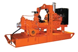
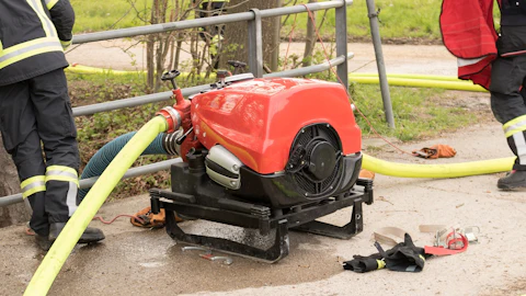
Godwin CD160M Dri-Prime pumps proved the best choice to handle the flow and lift required. Available with diesel engines or electric motors, the pumps are rated for 1,900 gpm at 260 ft. of head.
Two 150-hp electric drive versions served as the primary and lag pumps to meet flow demands, while a Critically Silenced 147-hp diesel version served as a backup. A standard 147-hp diesel model supported the entire system in the event of major storm surges or power outages.
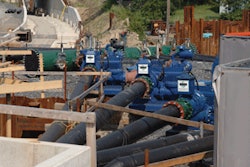
At roughly 11.5 ft. long and 4.5 ft. wide, the four pumps were compact enough to meet the space restrictions. However, the bypass would also require four, 20-ft. lengths of 8-in. flanged discharge hose; four 10-in. high-density polyethylene (HDPE) dip tubes with 10-in. flanges; and roughly 150 ft. of 18-in. HDPE pipe, adapters and elbows. All of these items, along with check valves, a discharge manifold, combo vents, a flanged reducer and ball valve, had to be fabricated and/or assembled on site within the 30' x 30' work area.
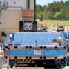
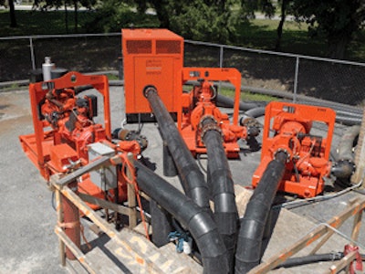
Working with C&D Contractors, Inc., Godwin's team of fusion technicians assembled the HDPE sections and connections in stages, starting from the discharge point at an emergency force main connection. A crane lifted the sections over the roughly 20-ft.-high pumping station building. The team then fused the approximately 100-ft. length of HDPE discharge pipe, tying it into the single, 18-in. outlet of the discharge manifold. On the inlet side, they connected a check valve to each of the four 8-in., 20-ft.-long discharge hoses that tied directly into each pump.
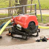
In the final stages of assembly, the pumps and their controllers were brought in and connected. The suction point also presented space limitations. The only pickup spot for flow was a large-diameter manhole located just before the pump station wet well. This became home to the four 10-in. HDPE dip tubes and four level transducers, leaving just enough room to install a sewer plug.
Despite the tight fit, the entire assembled system still provided adequate space for the contractors to move equipment in and out through the pumping station door.
Working out the logic
The plan for approaching the flow conditions was simple. The first (lead) and second (lag) electric drive pumps were equipped with 200-hp variable frequency drives (VFDs) incorporating level transducers and programmable logic controllers (PLCs) that allowed the VFDs to work together. Using these controls, Godwin engineers could identify and program system variables that could vary pump speed to keep up with the influent; start and stop pumps as demand required; and alternate lead and lag control between the pumps.
The VFDs worked to only deliver the flow necessary for system conditions. This approach lessens pump wear and tear and decreases the power surges and costs associated with peak demand on the pump. Likewise, the level transducers sensed the pressure as the water rose, then sent a signal to the VFD to speed or slow down the motor.
Since water turbulence can be a challenge when using a level transducer in a manhole, a perforated tube was inserted into the manhole to create a stilling well. This not only protected the transducers from debris, it rendered the turbulence undetectable, resulting in a cleaner signal, thus avoiding rapid cycling. The transducers also featured a level signal selector switch that took the average of both transducers, or switched from one to another if a signal went bad.
Pumping on a force main requires a variable head condition proportional to flow. When only one pump is running, the discharge head will be much lower than with all three pumps in operation. Excessive use of a single pump running at full speed with no head could potentially lead to cavitation and damage. The VFDs each had a PLC programmed to only allow a single pump operation to run up to a lower maximum speed, unless more than one pump was required to handle the flow.
The two diesel pumps were equipped with PrimeGuard Controllers and level transducers, and were controlled independent of the electric pumps. In an effort to exercise the pumps on a routine basis, the first diesel backup would start up once a week. The system backup pump would also start once a week, sending an alarm signal via its Chatter Box Auto Dialer to verify proper backup system function.
Since the Puncheon Run facility is in a residential area, the pumps had to operate with minimal noise levels. The combination of electric pumps and the Critically Silenced pump unit resulted in noise levels no greater than 68 dBA at 30 ft.
Technology proves key to success
The month-long bypass project was successfully completed, largely due to advanced pump technology. The ability to meet a wider range of flow requirements, including initiating backup pumping; routinely exercise the pumps and/or allow time for scheduled maintenance; and send alarm signals ensured reliability and responsiveness.
In addition, the electric pumps coupled with VFDs, PLCs and transducers were able to effectively manage the power requirements associated with drastically varying flow levels; decrease electricity costs associated with power surges; and minimize long-term pump wear.