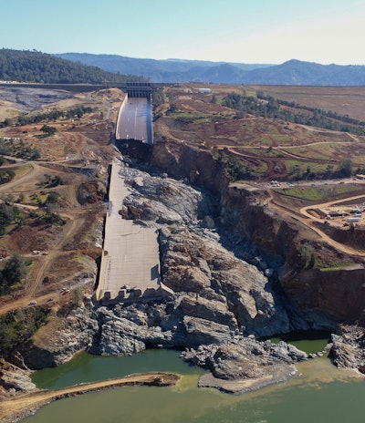
On February 7, 2017 Lake Oroville was rising due to a series of large storms. That resulted in the use of the Oroville Dam main spillway for flood control. But shortly after opening the main spillway, the California Department of Water Resources (DWR) noticed an unusual water-flow pattern and closed the spillway gates to inspect. Midway down the main spillway a section of concrete floor slab came loose and was swept down the spillway by water moving at about 100 feet per second—52,250 cubic feet per second (cfs). The damage was too much to repair quickly, and the need to use the spillway for flood control remained critical.
Over the next few days the DWR reopened the main spillway and the damaged area increased in size. It became evident that the rising lake level would cause flow over the adjacent emergency spillway weir for the first time in the dam’s history, so workers began to clear trees and prepare the area downhill. The main spillway sustained damage in what followed; massive erosion and the destruction of a significant portion of the spillway walls and slabs. The high velocity water created a canyon 150 feet deep in the lower half of the spillway. While this was happening the DWR was monitoring the risk to power line damage on the hillside above, potential flooding in the Hyatt Powerplant at the base of the dam due to erosion blocking a diversion channel, and the activation of the emergency spillway. The question now was what to do?
The dam
The Oroville Dam on the Feather River was built in the 1960’s and is located in the Sierra Nevada Mountains in northeastern California. It is the highest dam in the U.S. at 770 feet and the second largest reservoir in California, storing approximately 3.6 million acre-feet of water. It produces 841 megawatts of electricity, provides 25 million people with water, and irrigates 750,000 acres of farmland. It is an earthen dam with a concrete spillway and an emergency concrete weir for flood control.
The main spillway is 178 feet wide and 3,053 feet long with an elevation drop of 500 vertical feet. The original concrete floor thickness averaged 2 feet and the walls on either side varied from 20 to 34 feet in height. It’s used to control water levels for flood management and provide water deliveries for the environment, agriculture and water contractors.
Next to the main spillway is the emergency spillway with a 1,700 foot long concrete weir that passes additional lake overflow over natural terrain to the Feather River.
The need for speed
Ted Craddock, the California Department of Water Resources (DWR) Project Manager for the rehabilitation of the spillway project, said they quickly realized the entire main spillway would have to be removed and replaced with work occurring outside the November to April flood season.
The first task was to develop a plan for completing this massive undertaking with a very compressed schedule. A typical spillway project would take years to design and construct, but the team had only 8 months until the start of the next flood season.
Bringing a team of engineers together to begin the new design was the next big step and Craddock says that within a few weeks of the incident, over 100 engineers began design work. He adds, “We also realized that we needed to quickly select a general contractor as they needed to locate a large amount of equipment on the jobsite including crushing equipment and large capacity concrete batch plants.” So they solicited large contractors with proven capabilities in this area and invited them to bid the work, the bid period being only ten days. The Kiewit Corporation, Fairfield, California, was the winning bid and got the job.
Craddock said the design work started in March and was completed in June. Construction started in May with phase 1 construction work completed by Nov. 1 in 2017 and phase 2 work completed by Nov 1, 2018 before the start of the annual flood season.
The construction was scheduled to take two years in total. The task for phase 1 involved the repair and reconstruction of portions of the main spillway to accommodate potential flood water releases from the main spillway up to 100,000 cfs by the Nov. 1, 2017 milestone.
Construction in 2017—Phase 1
Jeff Petersen, Kiewit’s project manager for the Oroville Spillways Emergency Recovery Project, says that when they started on May 1, 2017, they had one month to mobilize 500 pieces of large equipment onto the jobsite, including a rock-crushing plant and two high capacity concrete batch plants, one for regular cast-in-place (CIP) concrete and one for roller-compacted concrete (RCC). Thirty-five construction trailers were also moved on site. “We hired over 100 people to start the project, the number eventually reaching 800 people not counting inspectors and DWR staff,” Petersen added
The challenge for the first year was to remove the damaged portion of the main spillway and make the main spillway serviceable to pass water-flows from the reservoir by Nov. 1, 2017. The work included:
- Minor patching and reinforcing the top 730 feet of the main spillway since this section was mostly undamaged.
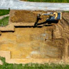
- Replacing the center 1,050 lineal feet of the main spillway where the most damage occurred. Workers excavated everything down to bedrock, cleaned and vacuumed 80,000 square yards of rock surface, installed rock anchors on 8-foot centers to secure the new concrete, installed sub-drains, and placed leveling RCC.
- Removing broken concrete and aggregate from the main spillway diversion pool and recycling it for use as concrete aggregate.
- Placing 370,000 cubic yards of RCC in the middle area of the main spillway including filling the 150-foot deep trench in the main spillway created by escaping water, and for construction on the emergency spillway.
Mike Rogers, Sr. Civil Engineer and Global Dams Practice Leader for Stantec, San Diego, Calif., worked with DWR to develop and monitor the RCC design features for the project, including concrete mixes and placement. He says part of the aggregates were recycled from the eroded rock dredged from the Feather River following the initial incident. The RCC mix and procedures were designed for quick and easy placement in high ambient summer temperatures, even into the difficult spillway rock foundation with large outcrops and small crack areas. He said they placed 370,000 cubic yards of RCC in 100 days in the center main spillway, including the backfill of the 150-foot deep trench caused by erosion during the initial incident. The exposed rock terrain at its most difficult point, had nearly vertical side slopes making for challenging placements.
A first for the industry, RCC was used to form the steep 4:1 slope of the main spillway using a series of horizontal placements with mechanical trimming to a rough 4:1 slope. A final 12-inch thick enriched RCC layer with a higher strength was placed on the final exposed 4:1 spillway chute surface using specialized equipment to create a strong wearing surface.
In another innovation, RCC was used to create temporary side walls in the RCC portion of the main spillway, including the use of Hilfiker Baskets for forming systems with smoothly placed shotcrete finishing. The walls were needed for the 2017-2018 winter season should the need arise to use the spillway during that interim construction period. Ultimately, the spillway was not used in 2017-2018 and the temporary walls were removed and the enriched RCC chute surface was covered with conventional CIP as designed in the other portions of the main spillway.
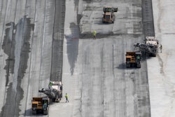
RCC was also used during the second season of work (2018) in the emergency spillway area to create what workers referred to as “the amphitheater,” a large spillway splash pad sloping downhill with a series of large sweeping 2-foot high steps to channelize flow, resembling a huge outdoor arena. Petersen says they used bulldozers controlled by GPS to place the RCC to the design grade. Then a track-hoe, also guided by GPS, with a custom-fitted vibratory plate attachment shaped and compacted the RCC. “However, it was the skill of the operator that was the most important in creating the final shape,” he added.
2018 Construction—Phase 2
Constructing the finished slabs and walls of the main spillway all occurred in the second year. The RCC work for the emergency spillway was also completed.
During the second season, workers completed the installation of rock anchors to hold the main spillway concrete in place, installed the finished the main spillway slabs, rebuilt the main spillway walls, constructed a “secant pile wall” consisting of 605 concrete piles, 3 feet in diameter, drilled into the bedrock at 35 to 65 feet in depth to prevent erosion, and repaired the four energy dissipaters or “dentates” located at the bottom of the main spillway.
In the main spillway, RCC was used to fill the major scour holes to bring the chute surface back up to the original design configuration, also becoming the base for the 3-foot thick cast-in-place finished concrete spillway slabs with the average total concrete thickness being 7.5 feet. These CIP checkerboard placements included one mat of epoxy rebar at the top of the slab and a mat of regular rebar at the bottom of each panel. Each panel was 37.5 by 30 feet.
The new walls for the main spillway ranged from 20 to 34 feet in height and were heavily reinforced. They were 2 feet in thickness at the top and 3 to 5 feet thick at the base. Kiewit built their own gang forms to place each the 30 foot wide sections.
Kiewit removed 12 to 15 inches of concrete from each surface of the four dentates at the bottom of the main spillway. The surfaces were replaced with highly reinforced concrete. The dentates direct the flow of water and reduce its force as it leaves the spillway. They must withstand as much as 5 million horsepower energy forces from the water.
Concrete
Nearly all the concrete was batched by the two batch plants on site, one for RCC and one for CIP. Petersen says the RCC mix included two aggregates, fly ash, cement, and ice-cooled mix-water to achieve placing temperatures of 85°F. “The mix was expected to achieve 3000 psi but cylinders broke much higher than that,” he added.
Joe Burke, senior engineer at DWR, says mixes for the main spillway CIP slabs and the walls included three aggregates, cement, fly-ash, silica fume, chilled water, and liquid nitrogen cooling to achieve 55°F placing temperatures. Coarse aggregates and fine aggregate were stored under shade. The mixes were designed to achieve minim strengths of 5000 psi and most of this concrete was placed at night when ambient temps were a little cooler.
Both the CIP and RCC walls were cured with a spray-on curing compound.
Challenges
Weather. Unfortunately work had to be scheduled during the hottest time of the year when the spillway would not be used. An extended heatwave in 2018 resulted in temperatures during the day as high as 117°F, made all the worse by the south facing main spillway. Petersen says nighttime temperatures were a little better but not much. Kiewit provided shade tents, an unending supply of water, crates of fruit to help workers stay hydrated, training to recognize heat stress, and an on-site medic.
Sloped concrete. Kiewit elected to use roller screeds on the 4 to 1 slopes (22.5 degree angles) of the main spillway and contacted Lura Enterprises to see if they had a high production solution. Dennis Lura, the company’s president, said their roller screeds could achieve the specified flatness standard in the 38 foot widths of the floor panels but Kiewit wanted the 3-inch slump concrete to be struck off moving in an uphill direction so a power unit with electric winches was designed to hold the screed and move it uphill at the touch of a button. The resulting 3,500 pound screed and power unit was built strong enough to be moved by crane. Lura says the screed roller was supported by two “CV joints” (booted joints encasing roller bearings) in the length of the screed to maintain flatness. Kiewit placed checkerboard panels each night, passing the screed over the fresh concrete four times, the last time being half an hour after placement as a final check. Workers used a walk-behind finishing machine with a pan float for the floating step, holding the machine in place by rope. The final finish was hand-troweled.
Sloped RCC. Rogers states that placing RCC at a steep 4:1 angle in the main spillway without forms was a first. Using Trackhoes with custom-built vibrating plates to create and shape the emergency spillway “auditorium” steps was also a first.
Project duration. The time frame to do the work was very short and was driven by the need to create a useable spillway for the 2017 flood season. The same was true for the 2018 construction season; the spillway had to be ready for the 2018 flood season starting on Nov 1.
Fire. Northern California experienced its deadliest wildfire season in the fall of 2018. The Oroville Dam is located 17 miles away from the town of Paradise and the Camp Fire. Workers were exposed to smoke from the fire and some were evacuated from their homes. There were also evacuation plans for the jobsite if needed.
Ready for use
The contract allowed for 165 construction days for the two seasons of work. When the spillway was first used on Feb. 7, 2017, a water flow of 52,250 cfs produced the first damage to the 24-inch thick spillway floor. In the succeeding next few days, main spillway flows were increased to 100,000 cfs in the spillway and water also flowed over the emergency spillway. By the time the high water levels began to recede the main spillway was damaged and out of commission. The emergency spillway was not damaged but uphill erosion threatened the structure. But now with the final completion of the construction anticipated in the summer of 2019, the main spillway is much stronger and engineers predict that 270,000 cfs water flows will be safe.