Most slabs-on-ground are unreinforced or nominally reinforced for crack-width control. When positioned in the upper or top portion of the slab thickness, steel reinforcement limits the widths of random cracks that may occur because of concrete shrinkage and temperature restraints, subbase settlement, applied loads or other issues.
This type of reinforcement is commonly called shrinkage and temperature reinforcement.
Shrinkage and temperature reinforcement is different than structural reinforcement. Structural reinforcement is typically placed in the bottom portion of the slab thickness to increase the slab's load capacity. Most structural slabs-on-ground have both top and bottom layers of reinforcement for controlling crack-widths and increasing load capacities. Because of constructability issues and costs associated with two layers of reinforcement, structural slabs-on-ground are not as common as nonstructural slabs.
While there are several reinforcing options for nonstructural slabs-on-ground, this article focuses on steel reinforcing bars and welded wire reinforcement for crack width control.
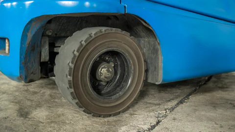
 Unrestricted crack width growth leads to spalled edges along out-of-joint cracks when exposed to wheeled traffic, especially hard-wheeled lift trucks.
The basics
Steel reinforcing bars and welded wire reinforcement will not prevent cracking. Reinforcement is basically dormant until the concrete cracks. After cracking, it becomes active and controls crack widths by restricting crack growth.
If slabs are placed on high quality subbases with uniform support and consist of low shrinkage concrete with joints properly installed with spacings of 15 feet or less, reinforcement is generally unnecessary. Most likely, there will be few random or out-of-joint cracking. If random cracks do occur, they should remain fairly tight because of the limited joint spacing and low concrete shrinkage thereby limiting future serviceability or maintenance issues.
When slabs are placed on problematic subbases with risks of non-uniform support or consist of moderate to high shrinkage concrete or joint spacings exceed 15 feet, then reinforcement is necessary to limit widths of cracks should they occur. As crack widths grow and approach about 35 mils (0.035 inches), the efficiency of load transfer through aggregate interlock diminishes and differential vertical movements across cracks or slab "rocking" can occur. When this happens, crack edges become exposed and edge spalling will likely occur, especially if the slab is exposed to wheeled traffic and especially hard-wheeled lift trucks. Once spalling starts, crack widths at the surface become wider and slab deterioration along cracks increase significantly.
When contraction joints are unacceptable and not installed, shrinkage and temperature reinforcement is required. This design approach is sometimes referred to as continuously reinforced or joint-less slabs and allows numerous, closely spaced (3 to 6 feet), fine cracks to occur throughout the slab.
 Unrestricted crack width growth leads to spalled edges along out-of-joint cracks when exposed to wheeled traffic, especially hard-wheeled lift trucks.
Crack control options
In general, there are two options for controlling cracks in slabs-on-ground: 1) control the location of cracking by installing contraction joints (does not control crack widths) or 2) control crack widths by installing reinforcement (does not control crack location).
With Option 1, we tell the slab where to crack and widths of contraction joints or cracks in the joints are largely controlled by the joint spacing and concrete shrinkage. As joint spacings and concrete shrinkage increases, joint widths increase. Similar to cracks, if joint widths approach about 35 mils, the efficiency of the aggregate interlock to transfer loads and prevent differential vertical movements across joints can be significantly reduced. For this reason, many designers use load-transfer devices including steel dowels, plates or continuous reinforcement through contraction joints to ensure positive load transfer and to restrict differential vertical movements across joints.
With Option 2, we allow slabs to crack randomly but control crack widths with steel reinforcing bars or welded wire reinforcement. Typically, contraction joints are not installed with this option. Instead, cracking occurs randomly forming numerous, tightly held together cracks. Because of appearance, this crack control option should always be discussed with the owner.
Cutting reinforcement at joints
Use caution when using both crack control options in the same slab. If too much reinforcement passes through contraction joints, joints become too stiff and may not crack and open as designed. When contraction joints fail to activate (i.e., crack and open) because of reinforcement, out-of-joint or random cracking typically occurs. If both options are used, it is necessary to limit the amount of reinforcement passing through joints to ensure proper activation.
Some designers specify to cut all the reinforcement at contraction joints while others may specify to cut every other bar or wire. By cutting every other bar or wire, the remaining reinforcement will help provide load-transfer and minimize differential panel movements but not restrict joints from activating. If the specifications and construction drawings do not indicate what to do with temperature and shrinkage reinforcement at joints, contractors should submit a request for information. Many times contractors are inappropriately blamed for out-of-joint cracking associated with this design issue.
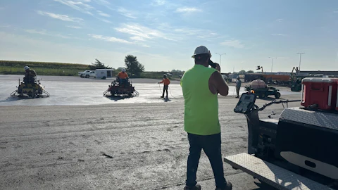
 The "hook and pull" method of moving welded wire reinforcement into the specified location is an ineffective method contractors should avoid.
Location of reinforcement
Steel reinforcing bars and welded wire reinforcement should be positioned in the upper third of the slab thickness because shrinkage and temperature cracks originate at the surface of the slab. Cracks are wider at the surface and narrow with depth. So, crack-control reinforcement should never be positioned below the slab's mid-depth. Reinforcement should also be placed low enough so saw cutting does not cut the reinforcement. For welded wire reinforcement, the Wire Reinforcement Institute recommends steel placement 2 inches below the surface or within the upper third of the slab thickness, whichever is closer to the surface. Designers typically specify the reinforcement position by specifying concrete cover (1 1/2 to 2 inches) for the reinforcement.
Positioning a single layer of reinforcement in the center or at mid-depth of the slab is not recommended (except for 4-inch-thick slabs). This is an all-purpose location where the designer hopes to increase the load capacity of the slab in addition to provide crack-width control. However, positioning reinforcement in the middle of the slab will not effectively accomplish either objective.
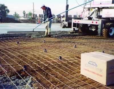
Steel reinforcing and welded wire reinforcement should be supported and sufficiently tied together to minimize movements during concrete placing and finishing operations. Otherwise, reinforcement may not be properly located in the slab. Support reinforcement with chairs or precast-concrete bar supports. Chairs should have sand or base plates and bars should have at least a 4-inch square base to ensure they don't sink into the subbase. Use support spacings that ensure reinforcement does not sag between supports or is not pushed down by foot traffic or fresh concrete. Flexible reinforcement including welded wire reinforcement requires closer support spacing. In addition to specifying the type and amount of reinforcement, designers should specify the type and spacing of supports to ensure proper positioning of the reinforcement.
Welded wire reinforcement should never be placed on the ground and pulled into position after concrete placement. The "hook and pull" technique always results in improperly positioned reinforcement. How can workers uniformly "hook and pull" welded wire reinforcement into the specified location while standing on the reinforcement?
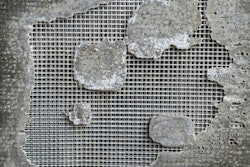
 Reinforcement partially buried in the subbase does not provide crack width control. Without supporting chairs or pre-cast concrete blocks, reinforcement typically ends up in the bottom of the slab or buried in the subbase.
Placement tolerances
Vertical placement tolerance for reinforcement in slabs-on-ground is ± 3/4 inch from the specified location. For slab thicknesses 12 inches or less, the concrete cover tolerance is - 3/8 inch measured perpendicular to the concrete surface and the reduction in cover cannot exceed one-third of the specified cover. In many cases, the cover tolerance overrides the vertical placement tolerance. Properly placing and supporting reinforcement will help ensure compliance with these vertical placement tolerances.
This article was originally published on Feb. 25, 2013.
References:
ACI 117-06. "Specification for Tolerances for Concrete Construction and Materials"
ACI 302.1R-04. "Guide for Concrete Floor and Slab Construction"
ACI 360R-06. "Deign of Slabs-on-ground"
ASCC Position Statement #2. "Location of Rolled Welded Wire Fabric in Concrete"
WRI Tech Facts. "Supports Are Needed for Long-Term Performance of Welded Wire Reinforcement in Slab-on-grade" (TF 702-R-08)
WRI Tech Facts. "How to Specify, Order and Use Welded Wire Reinforcement" (TF 202-R-03)