Concrete volume changes due to changes in moisture and temperature. As concrete dries, it shrinks. Length change related to drying shrinkage for unreinforced concrete can range up to 0.08% whereas normal reinforced concrete is about 0.02% to 0.03% due to the internal restraint associated with the reinforcing.[1]
For an unreinforced or lightly reinforced 100 ft. wall, drying shrinkage tries to shorten the wall up to about one inch. If the wall is normally reinforced, shortening is reduced to about 1/4 to 3/8 of an inch. With regards to thermal contraction, our 100 ft. wall subjected to a 50º F temperature drop tries to shorten an additional 5/8 of an inch.
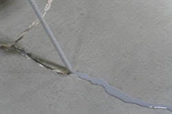
Wall shortening from concrete drying shrinkage and/or thermal cooling combined with restraints including wall corners, intersecting walls and foundations with dowel bars causes vertical cracks to form (see figure 1). Due to shrinkage and restraints that resist wall shortening, tensile stresses form and when stresses exceed the tensile capacity of the concrete, cracking occurs.
Concrete Shrinkage + Restraints = Tensile Stresses = Wall Cracks
Another way of thinking about this shrinkage and restraint behavior is to place our 100 ft. wall in outer space. Floating in space without restraints, the wall could freely shrink or shorten to a new length without cracking.
Back on earth with wall restraints, cracks form and relieve the tensile stresses created by the concrete shrinkage. If wall stresses are not sufficiently relieved by cracking, new cracks occur between previously formed cracks. As illustrated in Figure 1, most wall cracks start at the bottom and grow upwards due to the rigid restraint created by the foundation.
 Figure 1. Typical vertical wall cracking if no joints are provided. Also, reentry corner cracks can form due to stress concentrations at interior corners that can contribute to vertical wall cracking.
Crack Control Options
The risk of wall cracking can be reduced by minimizing the root causes. Reducing the water content of the concrete and/or including a shrinkage reducing admixture can help reduce the risk of cracking or at least the severity of cracking. Concrete shrinkage is strongly dependent on the total water content of the concrete. So, reducing the water content, reduces concrete drying shrinkage and the risk of vertical wall cracks. If wall cracks are a concern, discuss concrete mix options to reduce drying shrinkage with your concrete supplier.
Most likely, it will not be possible to reduce wall restraints and concrete temperature variations. For this reason, contraction joints and horizontal reinforcing are the best options to control random vertical cracks. Of course, the designer is responsible for establishing the mix design requirements in addition to specifying either contraction joints or horizontal reinforcing or both and the related details.
Option 1. Contraction Joints
Installing contraction joints is an economical and simple way to control the location of vertical cracks. Contraction joints are weakened planes created by reducing wall thicknesses, reinforcing or both so cracking occurs within the joints. As concrete dries and tensile stresses increase, cracks occur at the thinner sections within the contraction joints.
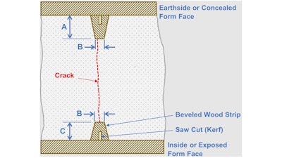
Contraction joints are made using wooden, rubber, plastic, or metal strips attached to the inside form faces as illustrated in Figure 2. Strips create narrow vertical grooves on both sides of the wall creating thinner wall sections. Total depth of the two grooves should be at least 1/4 of the wall thickness to ensure the thinner section is sufficiently weakened to control the location of cracks.
 Figure 2. Details for forming contraction joints in walls.
| Wall Thickness | 6 in. | 8 in. | 10 in. |
| A | 1 in. | 1 1/4 in. | 1 3/4 in.* |
| B | 1/2 in. | 1/2 in. | 1/2 in. |
| C | 3/4 in. | 3/4 in. | 3/4 in. |
*May conflict with horizontal rebar if the wall has two mats
In general, and as illustrated in Figure 3, recommended joint spacing is the height of the wall for walls taller than about 12 ft. and three times the wall height for walls less than about 8 ft.[2] Due to wall restraints associated with corners and intersecting walls, install joints within 10 ft. to 15 ft. of wall corners and intersections. These recommendations recognize that the upper portion of the wall is likely to cool and shrink faster than the lower portion that is more restrained. Both conditions create tensile stresses within walls that create vertical cracks. Consider placing joints at abrupt wall changes, in line with openings to help control reentry corner cracks, and in locations to create an acceptable visual appearance. While Figure 3 illustrates wall jointing recommendations, each wall should be evaluated to determine the best joint locations and spacings.
 Figure 3. Recommended contraction joint locations and spacings.
Where h < 8 ft., s = 3 x h
Where h > 12 ft., s = h
smax = 25 ft.
Exterior grooves can be sealed with a non-sag, elastomeric sealant (e.g., polyurethanes and silicones) to prevent penetration of cold air, moisture, water, and insects through cracks. Sealants can also be used in interior grooves to conceal cracks.
Option 2. Reinforcing
Horizontal wall reinforcing controls the width of shrinkage cracks – not the location. How tightly cracks are held together depends on the amount and spacing of the reinforcing. Increasing the amount or reducing the spacing of reinforcing passing through cracks, decreases crack widths. In many cases, this is the designer’s choice to control vertical wall cracks. With this design choice, don’t expect a crack-free wall. Expect random cracking to occur but crack widths should be limited by the amount of wall (horizontal) reinforcing.
Using both load and building code requirements, designers establish the required reinforcing for walls. Horizontal reinforcing may be determined by load conditions, minimum code requirements to ensure structural integrity, or minimum “temperature and shrinkage” reinforcing as specified by building codes or the local building officials.
 Kim Basham
The amount of horizontal reinforcing can be quantified by computing the reinforcing percentage that is based on the reinforcing and wall thickness. For example, #4 at 12 in. on center located in the middle of an 8 in. thick wall yields a reinforcing percentage of 0.21%.[3] While 0.21% exceeds the minimum 0.18% temperature and shrinkage reinforcing specified by the International Building Code, it may not hold the vertical wall cracks sufficiently tight to satisfy the wall’s function or the owner’s expectations.
If our example wall was 23 ft. long with 0.21% horizontal reinforcing, approximate crack widths exceeding about 0.010 in. should be expected. To limit cracks widths to about 0.010 in. and 0.004 in. (watertight), reinforcing percentages would need to be increased to approximately 0.30% and 0.55%, respectively.[4] To achieve a 0.30% value, the reinforcing would need to be #4 at 8 in. on center and for 0.55%, #5 at 7 in. or #6 at 10 in. on center, respectively.
As shown with the simple wall example (figure 3), significant amounts of horizontal reinforcing are required to keep vertical crack widths narrow. For watertight retaining walls, the minimum wall thickness is typically 10 in. with two mats of reinforcing with significant amounts of horizontal reinforcing to keep crack widths less than 0.004 in. Designers commonly increase the amount of horizontal reinforcing in the lower 3-5 ft. of walls to help control the width of cracks that start at the bottom and grow upwards.
Combining Options 1 & 2
Contraction joints and reinforcing can be combined to control vertical cracking but if too much reinforcing crosses joints, joints may not be sufficiently weakened to activate and control the cracking location. Recommendations for reinforcing at contraction joints range from: stopping all reinforcing 2-3 in. from the joint, allowing 50% or another amount of the reinforcing to continue through the joint, and discontinuing all reinforcement and installing slip dowels to maintain alignment of the adjacent wall surfaces.
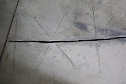
 A crack compactor card can help you determine the width of the crack in question. Place the card on the crack and align the line that matches the crack width.Kim Basham
Crack Repair Options
Reducing concrete shrinkage and wall restraints and installing contraction joints with or without horizontal reinforcement does not ensure that random or out-of-joint cracks will not occur. If out-of-joint cracking does occur, there are several repair options that can be used to either seal or structurally repair cracks if needed.
- Route and Seal. The simplest and most economical means to repair vertical cracks regardless of crack widths. It is a nonstructural repair that consists of routing or enlarging the crack to create a V-shaped sealant reservoir and then filling the reservoir with a non-sag, elastomeric sealant (e.g., polyurethanes and silicones).
- Polyurethane Injection. Inject wet or leaky cracks with polyurethane resins that combine with water to form an expanding and flexible gel to choke off leaks and seal cracks. This technique is a full-depth and lasting crack repair.
- Epoxy Injection. Welds or bonds crack faces together and restores the soundness and integrity of the concrete. However, if the injected cracks are active (still opening due to continued concrete shrinkage or acting as joints to relieve thermal stresses) new cracks may form adjacent to the repaired cracks.
This article has presented two proven crack control options for walls. Unfortunately, a third crack control option is often used: let it crack. This approach assumes you will deal with cracks after they occur. Using this option can become time-consuming and expensive if any party misinterprets the cracks as defective concrete or workmanship that jeopardizes the structural integrity, function, or service life of the structure. It is better to be proactive and consider crack control options and crack expectations before starting the job.
About the author
Kim Basham is president of KB Engineering, LLC which provides engineering services to the concrete industry and a registered professional engineer in 19 states. Dr. Basham also teaches seminars and workshops dealing with all aspects of concrete including concrete technology, concrete construction, and troubleshooting for the American Concrete Institute, World of Concrete, and other concrete/construction organizations. He can be reached at [email protected].
References
[1] Kosmatka, S. H. and Wilson, M. L., Design and Control of Concrete Mixtures, 5th Edition, 2011, pp. 180, Portland Cement Association, www.cement.org
[2] ACI 224.3R-95 Joints in Concrete Construction, p. 32, American Concrete Institute, www.concrete.org;
[3] [(0.20 in2/ft)/(8 in. x 12 in.)] x 100 = 0.21%
[4] Kianoush, M. R., Acaran, M., and Dullerud, E., Cracking in Liquid-Containing Structures, Selecting the appropriate temperature and shrinkage reinforcement, Concrete International, pp. 62 – 66, April 2006, American Concrete Institute, www.concrete.org.