In September 2010, the New Orleans District Corps of Engineers was trying to determine if a stage control structure built near Zachary, LA, in East Baton Rouge Parish was constructed according to design tolerances. The construction contractor's surveyor had collected 12,000 shots on the structure surface with a total station without being able to determine if it was within the strict tolerances required. Something more powerful was needed - and laser scanning turned out to be the answer.
The Amite River and its tributary, the Comite River, are the major causes of catastrophic flooding in the Baton Rouge metro area. In 2001, the U.S. Army Corps of Engineers, the state, the Amite River & Tributaries Study Authority and East Baton Rouge Parish signed an agreement to develop a regional solution called the Comite River Diversion Canal Project. Its purpose is to divert about 50% of the flood waters from the Upper Comite River to the Mississippi River.
Little room for deviation
Due for completion in 2016, the Comite River Diversion Canal Project involves construction of a 12-mile-long diversion channel from the Comite River to the Mississippi River; a diversion structure at the Comite River; guide levees; the Lilly Bayou stage control structure; and several drop structures where the diversion channel intersects with roads, railroad bridges and bayous. As of 2008, the total estimated cost of the project was $187 million.
The Lilly Bayou Control Structure will dissipate the energy of water flowing between the Comite and the Mississippi from a higher to lower elevation, according to Rick Tillman, structural engineer with the Corps. The energy will dissipate as water flows over a spillway featuring an elevated weir.
The $27.6 million second phase of the project consists of the excavation and construction of the concrete control structure, a stilling basin and an outflow channel. The main surface slab was designed to have a 1 to 5 (1v: 5h) slope, a several feet thick substructure of mass concrete and large baffle blocks filling the stilling basin at the bottom constructed of 3,000-psi concrete. A 1-foot-thick, 5,000-psi concrete overlay was also placed on top of the substructure to handle the compressive force and abrasion generated by rushing flood waters.
At no more than 1/8 inch of deviation for every 10 feet of surface, the elevation tolerance on the structure is uncommonly tight, notes Tillman. "That's out of the ordinary for the [Corps'] New Orleans District to design; however, it's not unusual for the purpose of the structure," he points out. "We have flow velocities that exceed 40 feet per second. At those velocities, you can get cavitation and if you have unevenness on the surface, it can tear a hole and tear the structure apart. That's why you have to have these tight tolerances."
After the structure was built, however, deviations from the elevation tolerance on the sloped face were plainly visible using a straight edge. Determining the extent to which the structure was out of tolerance promised to be quite a task in itself.
The difference: quantity of points
The Corps' lead engineering technician, Dwayne Blanchard, had previously experienced successful scanning projects completed for the division by Dale Stockstill & Associates (DS&A). He recommended that Tillman ask us about scanning the structure.
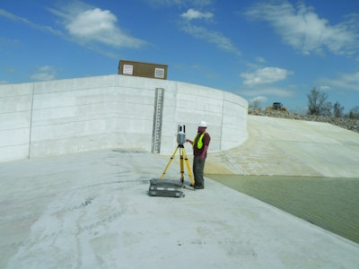
Eager to demonstrate the potential of scanning to the Corps, I agreed to perform the scan and data analysis without a task order. After obtaining the coordinates for the PK nails that were already in place from the construction company's project surveyor, our crew checked them with a GPT-3105W reflectorless total station from Topcon Positioning Systems, and then started the scan using a Topcon GLS-1000 laser scanner.
The elevation did not adhere to tolerance throughout the structure surface, but the X and Y axes were fairly close to tolerance. So the crew performed the scans from the existing control point, which was in place at the top and bottom of the large structure, knowing that the two scans could be corrected during the cloud registration process.
Tillman notes that scanning provided much richer surface detail than shooting in less time than a total station. "You can obtain those results on conventional total stations, but this is much quicker," he says. "They scanned the entire surface of this flume - I think it took them two to four hours - and they had something like 7.5 million points. It took about three days to collect about 12,000 points with the conventional total station."
After the initial scan was completed at the top of the structure, the data file was downloaded for the engineers to view in the construction trailer while the second scan was being taken. It didn't take long for Tillman's question to be answered - the millions of points collected on the surface clearly displayed undulations, ridges, dips and humps in the structure.
DS&A technicians used a PolyWorks routine to "color map" the deviations as related to the design plane. DS&A technicians provided traditional cross sections at specified intervals. But because the surface was so large and tolerances were so tight, many hundreds of sections would have been required just to view a small portion of the slope.
DS&A's technicians went to work programming. They modified some existing routines in their PolyWorks software to generate an ascii-type EM file - a format favored by the New Orleans District - that converts the point cloud data to a grid every foot laterally and half a foot longitudinally going down the slope. This programming had to be refined several times to deal with file size and computer processing speed.
After the program was refined, it extracted traditional points (point number, Northing, Easting, elevation and code) from the cloud at the specified intervals and wrote them out to an ascii file. This file was then converted to the New Orleans District's EM file format, enabling the data to be loaded into the district's programs for analysis by its engineers and technicians.
In addition to the EM file, the District Engineers requested a contour map - but not just any contour map.
The Corps engineers requested a CAD drawing that depicted the 1v: 5h slope as horizontal and contours that were related to the design plane. DS&A's technicians rose to the challenge and created a process that flattened the data onto the slope, while maintaining the original project stationing. This required application of a precise scale factor to the data on the slope, i.e., essentially squeezing the hypotenuse down to the base of the triangle. The contour interval was small (five hundredths of an inch) and directly in proportion to the original design.
Officially scanning
After the Corps received the data in a manner that was easily understandable to all Corps personnel involved - without the need to learn new software or go to a seminar to learn how to interpret a color map - it made the project official. It issued a task order to survey and scan the structure. Corps policies required that the data be recollected because the previous data provided by the contractor were accepted before the scan was performed.
DS&A's crew returned to the project site and started from scratch, checking the project Permanent Bench Mark (PBM) with their Topcon GPS units, running precise three-wire level loops from the PBM to the PK nails on the top and bottom of the structure with its Topcon AT-G1 AutoLevel.
I instructed the crew to use its GPT-3105W reflectorless total station in conjunction with its Topcon DL-500 digital level to obtain data under water and mud covering the stilling basin that could not be pumped out. The total station shot the digital level rod for the horizontal position, while the DL-500 obtained a precise elevation for each shot. The additional data obtained under the water were checked, compared and incorporated into the point cloud data.
Again, the data reflected the deviations from the design criteria and the deliverables were remade using the new data. As of early spring 2011, a process for correcting the structure's elevations was being worked out.
Based on this project, Tillman is a believer in the use of scanning technology to determine adherence to specifications on structures of such large scale. "I see other applications of its use that would be beneficial," he says, "such as repeat-type surveys that we have to do periodically for movement or settlement."
Billy Alan Chavers, RLS is the owner of Dale Stockstill & Associates, Carriere, MS, a leading provider of surveying, mapping and laser scanning services on the Gulf Coast.

