By Thomas Guerette
In the winter of 2016, the Rhode Island Department of Transportation (RIDOT) sent an advertisement to contractors for demolition services for the old Sakonnet River Bridge’s superstructure, which was to be removed and disposed. On the cold winter morning of Dec. 1, 2016, bids were opened and read aloud, and it was determined that NDA member S&R Corporation of Lowell, Massachusetts, had submitted the winning bid over six other bidders.
A complicated bridge configuration
At the time of award, the old Sakonnet River Bridge had been partially demolished to allow room for the new Sakonnet River Bridge’s approach spans, and consisted of 17 remaining spans plus the remaining ramp spans 1L and 2L. The Sakonnet River Bridge ended (or began, in this case) abruptly at span 17 in Tiverton, RI, across the Sakonnet River and ended at the west abutment in Portsmouth, RI, some 2,274 feet away.

The Sakonnet River Bridge had two separate concrete roadways: one for northbound traffic and one for southbound traffic. The concrete roadways on the approach girder spans consisted of 9-inch-thick reinforced concrete with an 1- to 1.5-inch asphalt top mix, while the roadways on the three truss spans consisted of an orthotropic deck configuration, where the concrete roadway was constructed of a steel grid encased in concrete to provide lateral and transverse stiffness to the bridge’s structure. The steel grid was welded to the bridge’s deck support structure members and became the roadway on the truss/arch spans of the bridge. The Sakonnet River Bridge’s deck was supported on a series of steel cross beams lying transversely every 6 feet on center to one another, atop the steel support girders and adjacent floor beams.
Tight constraints
The project documents required that the entire superstructure inclusive of steel bents be removed to the top of the concrete piers and abutments.
The Sakonnet River, with its brutal eight-knot current and 7.5-foot tidal drop, flowed under the bridge and was to remain open to marine traffic during all stages of demolition, except for a short window of time that the channel could be closed while the main center arch span was removed. This time constraint required development of a plan that provided the least amount of scheduled channel closure. Other constraints included setup and maintenance of several “marine safety zones” for all water-accessible areas under the entire bridge so local mariners and recreational boaters could easily identify the work zones and the accessible areas of the waterway adjacent to the ridge.
Directly under and adjacent to truss span 12 was an open and very active recreational boat ramp that had to remain in operation during the demolition tasks. The new Sakonnet River Bridge’s southbound breakdown lane was the main access to the old Sakonnet River Bridge work area for all deck removal-related work, so establishment of traffic controls and construction of a temporary access road was necessary just to gain access to the bridge. Other constraints included a “no stockpiling” or “material processing” covenant. Due to the constrained area around the bridge and considering the residential setting adjacent to the bridge, RIDOT was particularly concerned about creating a negative visual impact to the local residents and traveling public, so every piece of bridge removed had to be cut “truck size” and direct loaded and hauled off the job on a daily basis, making use of conventional steel shears and hydraulic impact hammers.
The project documents and environmental permits prohibited use of explosives and prevented anything from falling into the water during demolition, including concrete, steel and hand tools. Due to such constraints, blasting was prohibited as a methodology for this project. Environmental permits prohibited placement of any construction or equipment below the mean, high, high water mark (MHHW), so construction of temporary trestles or access platforms or roadways was also prohibited, which significantly added to the access challenges on this project.
Managing a tough project
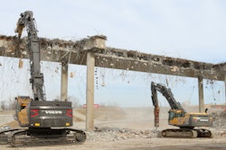
The old Sakonnet River Bridge consisted of the removal of 17 bridge spans and two ramp spans over both water and land. Nine of the 17 spans were over water, while the remaining spans were in residential neighborhoods and crossed directly over three separate roadways that had to remain open for traffic in both the morning and afternoon every day, which provided a very short window of work to remove structural members directly overhead. Work time on these spans equated to about six hours per day, while work occurred directly overhead was done as soon as the last segment of bridge was removed for the day — a full removal of heavy equipment, debris, traffic controls and street sweeping had to occur immediately and be completed by 2:30 p.m. each day for traffic to pass by again.
To prevent debris from falling to the ground or entering the waterway below the bridge, the entire bridge was shielded from span 17 to span 1 with a custom fabricated debris netting that was able to both contain loose debris also had a special second woven mesh liner to contain the slurry created from concrete deck sawing operations. As the deck was removed above the netting in each span, crews would remove each net to make way for steel removal operations. The debris shielding consumed some 136,500 square feet of debris netting hung over 4,000 attachment points.
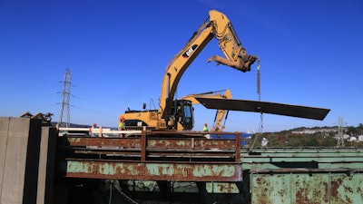
To remain compliant with the no stockpiling or material preparation contingent of the specifications, S&R had to develop demolition procedures that would allow for maximum production and ease of material handling. It was decided that the 2,274 liner feet of twin 28-foot-wide concrete road decks would be cut into 14-inch by 6-inch panels and picked off the steel with hydraulic excavators. S&R established two separate deck removal crews, and each crew used a 75-horsepower diesel concrete saw, one Cat-321DLCR excavator and one 10,000-pound rough terrain telescopic forklift. The forklift shared double duty by pulling removed debris from each crew and brought each segment of demolished material to the bridge’s west abutment where a third hydraulic excavator handled daily material truck loading chores. The twin deck demo crews removed approximately 18 feet of deck full width and edge-to-edge. At that point, deck cutting temporarily ceased, the underlying debris nets were removed and the aerial burning crews set out onto the steel framing tied off in yo-yo harnesses. They then began the task of cutting exposed cross beams, stringer beams, steel sidewalks and steel median plates from the bridge’s superstructure, leaving only the steel girders, floor beams, support bents and lower lateral braces remaining behind them as they worked from east to west, backing themselves off the bridge’s superstructure.
Steel girder and bent demo started at ramp spans 1L/2L and span 17, and following the deck demolition crews, a Liebherr LR1200 275-ton crawler crane was mobilized and began the task of removing the 100,000-pound plate graders and support bents with a separate demolition crew as the deck crews continued their task of removing the 130,000 square feet of bridge deck ahead of them.
Spans 13 and 14 comprised heavy built-up plate girders of 100 feet in length and each weighing 100,000 pounds. This proved quite a challenge, as access to the north was restricted by shallow water — much too shallow for a big deck barge and crawler crane — and the new Sakonnet River Bridge, only 35 feet away to the south, did not leave enough room for the massive boom and pendants of the 275-ton crawler crane to fit between. S&R had to improvise and mobilize a 600-ton hydraulic truck crane, set it up in the 35-foot-wide gap between the old Sakonnet River Bridge and the new Sakonnet River Bridge, and used this crane to reach both girders in both spans. Each outside girder was at a radius of an estimated 90 feet away.
As work progressed, the next challenge was to figure out how to lower the truss/arch spans in the tight area between the two bridges, keep the channel restrictions to a minimum, and provide room for cranes, barges, tug boats and boom lifts to fit between the north side of the old bridge superstructure and the high tension power lines positioned just some 90 feet away to the north of the old bridge. S&R and its engineers decided early in the process that the best way to overcome these constraints would be to disassemble the 243-foot-long approach trusses in manageable sections, beginning at each rest pier and working backward to the main span, similarly as to how it was constructed in 1955. The main center arch span was going to be lowered in an approximate 180-foot-long segment, weighing in at some 800,000 pounds, by support jacks mounted to a barge array below in a separate operation after the truss spans had been removed to a certain point. Although conceptually simple, this required significant bracing be fabricated and installed on piers 10 and 11 to offer support to the remaining portion of truss spans and arch span that would remain balanced on top of these piers. Each remaining truss/arch segment was estimated to weigh 200 tons. In order to accomplish this, S&R crews fabricated and installed 8-inch, 50-feet long pipe supports, consisting of 30-inch diameter, 0.75-inch wall pipe piling. Each support tube was in excess of 15,000 pounds and attached to the piers by 1- to 1.5-inch coil rods bolted through the 8-foot-thick concrete piers and secured to the bridges superstructure with 1-inch diameter grade bolts to resist the forces of the 200-ton sections that would remain after the center arch was lowered.

Once in alignment, the jack system was fired up and spacer barrels inserted in each leg of the four-leg jacking system until all four of the upper connection plates were just short of contacting the bridges lower chords. At this point, crews stationed in boom lifts atop the bridge inserted shims on the connection plates so that the four jack legs were level with one another. Then the jack system took up the load while the two jacking barges were monitored for even submergence under the 400-ton bridge load to maintain level. After the jack operator had confirmed that the jack system had the load of the bridge, four two-man burning crews were sent up on four 135-foot boom lifts stationed on nearby barges. Once given the signal, they began the tedious procedure of cutting one bridge member at a time, evenly releasing the load of the bridge from its superstructure frame where it had been supported since 1955 to the jack/barge system below. Once every initial cut was made, the burning crews were instructed by radio to begin “cut #2 and #3” until the load was fully released onto the jacks. The burning crews stayed with the bridge segment for a few cycles of the jack lowering to ensure that the arch segment was clear of the remaining bridge frame and no interferences needed to be dealt with during lowering. Then began the five-hour-long descent of the arch to barges 68 feet below. Once the jacks had lowered the arch segment as low as it could go, the arch segment was lashed to the barges decks with wire ropes and secured firmly for its 6-mile push up the Sakonnet River to a marine salvage yard for additional disassembly.
Shallow waters and small spaces
The next challenge in this project was in the removing of continuous plate girder on spans 7, 8 and 9, which was over very shallow water on the Portsmouth side of the project where water meets shoreline. The water depth at spans 7, 8 and 9 was much too shallow, and the room between piers was much too narrow to place the 180-foot by 60-foot deck barge and large crawler crane. S&R had to mobilize a smaller 148-foot by 48-foot deck barge equipped that with a 130-ton telescoping boom hydraulic crawler crane so that it could be pushed under the new Sakonnet River Bridge and positioned under the old Sakonnet River Bridge between the floor beams and plate girders of old bridge. This was necessary to get into the right position to remove the heavy 1,000-per-foot plate girders in manageable sections. Again, similar to the arch/truss dismantling, because of the tight area to maneuver around piers 7, 8 and 9, the use of a large crane was not possible. In order to use the smaller crane/barge, the entire three girder spans at 7, 8 and 9 needed to be propped up on temporary supports so it wouldn’t collapse during steel removal.

The girders and bents at spans 1 through 6 consisted of smaller rolled girder shapes and were much lighter that previous girders encountered. These removals were completed by using the 170-ton crane placed on the bridge deck in spans 5 and 4 and from the adjacent ground for spans 1, 2 and 3.
Project restoration activities included removal of the temporary access roadway at the west abutment, rough and finish grading, loaming and general highway seeding of all disturbed areas in Portsmouth and Tiverton, provision of 10,000 square yards of rip rap revetment stone and geotextile fabric along the Portsmouth shoreline, and removal of erosion and traffic controls.
A successful removal
Overcoming the challenges of this project was no easy feat. The S&R team was proud of the work they did on the Sakonnet River Bridge project, particularly as it relates to improvisation and smart problem-solving.
Thomas Guerette heads up S&R Corporation’s Demolition Division. He is responsible for the demolition divisions purchasing requirements, and provides oversight for project development, project management and estimating. Tom also expands S&R’s existing client base by exploring bidding opportunities in geographic markets outside of New England.