Meeting the millimeter (mm) accuracies required by job specs is extremely difficult. Even the best operators or grade control systems will have difficulty achieving the desired results if the grader is not well maintained or properly set up.
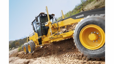
Rick Fines, motor grader product manager, Volvo Construction Equipment, reports that most difficulties hitting grade result from improper adjustment of the turn circle and blade lift contact points. “It comes down to operator experience, circle adjustments and visibility,” he says.
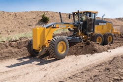
The most important maintenance items are in the circle and moldboard system; circle wear inserts; cylinder ball joint shims; moldboard cutting edges; circle and pinion teeth; moldboard pivot joint; and saddle assembly, according to Mike Ackermann, motor grader product marketing manager, John Deere Construction and Forestry. “As these components wear, you introduce more play into the system and play is not a good thing,” he explains. “The operator or grade control system tries to hold a specific grade, but the play in the system changes the elevation of the cutting edge. The electronics or operator can’t detect it and you are off grade. Because this is so critical, the John Deere offering requires no measuring to return the circle and moldboard back to factory specs. Just make the moldboard adjustments utilizing the jackscrews and replace circle wear inserts.”
Play in the turning circle, lift cylinders and moldboard slide should be checked daily and as the machine runs throughout a shift. “No movement is acceptable, which is why Caterpillar provides easy access and adjustment to these critical areas,” says Wade Porter, motor grader market professional, Caterpillar. “When these areas start to wear and require adjustment and/or replacement, the operator (especially a finish blade operator) will feel it and know that it is time for maintenance. The joints will become ‘sloppy and loose,’ negatively affecting the finished surface.”
To check for excess wear, lift the drawbar, circle and moldboard off the ground. “If the lift cylinder rods move without immediate cutting edge movement, this linkage is considered loose and needs to be adjusted properly,” says Porter. “The moldboard will begin to ‘chatter’ when the moldboard slide rail inserts need to be adjusted.
“Chattering is when the moldboard wiggles back and forth, fore and aft,” Porter continues. “This creates a washboard effect on the finished surface. Inspect by removing the end cap for the slide rail inserts, lifting the moldboard in the air and checking gaps between the insert and the rail. The drawbar wear inserts can be checked by raising the moldboard off the ground and inspecting for a gap between the wear insert and the drawbar plate.”
Some items can be monitored while operating the machine. “Cylinder ball joint wear can be pretty easy to see from the operator seat,” says Ackerman. “Always keep an eye on the upper saddle assembly and trunnion, and service as needed. The other aspect is lift cylinder reaction. [On the John Deere motor grader], if the lift cylinder gets to where it does not react as it should, the operator can recalibrate the cylinder performance back to factory specs right in the monitor.”
Speed and power are critical when positioning a blade for final grade. “As far as performance is concerned, I think it is a matter of speed and power of your circle turn system,” says Fines. “The circle turn is one of the highest duty cycle functions on a motor grader. A good operator is constantly adjusting the circle turn and blade lift.” To address this issue, Volvo uses two turn pinions instead of one. “It spreads the wear over two points instead of one.”
Volvo recommends checking the clearance of the blade lift cylinder ball and socket arrangement every 250 hours. “Most major manufacturers make them either replaceable or adjustable,” says Fines. “Ours is adjusted by removing shims. You don’t want more than 1/16-in. play. If it is more than 1/16 in., then pull a shim out.”
If you are in the market for a new or used motor grader, carefully evaluate the ease of servicing wear points. “If it is difficult to maintain, it doesn’t get done or it takes longer to get done, which drives cost,” says Porter. “If the grader isn’t maintained properly, the ability to finish will suffer. This is why Cat graders have easily accessible wear inserts with shimless designs wherever possible to minimize time.” This includes drawbar and slide rail adjustment points.
Being able to make quick adjustments adds to the grader’s versatility. “Sometimes a grader operator might not know they have to finish grade until the afternoon, when they are told to head to a different location on the jobsite,” says Porter. “So they might need to make some quick adjustments to pull up the slack in these key areas. In addition, the cylinder rod mounts need to be kept tight, which is why we provide replaceable wear inserts and bushings in the lift cylinders and link bar.”
Focus on the Cutting Edge
The cutting edge is perhaps the most important component on a grader when it comes to maintaining the accuracy of a cut.
“Make sure the cutting edge is replaced if it becomes worn unevenly,” says Porter. Cutting edge wear can occur in the middle as well as the corners, creating an uneven surface. “Maintain straight cutting edges by trimming them with a torch or, if the wear is not severe, by dragging the cutting edges on a smooth concrete surface. Replace edges before wear occurs on the bottom of the moldboard and reduces cutting edge support.”
A project with very tight specs demands more attention to the cutting edge. “It may even require cutting edge replacement every few days,” says Ackerman. “You want to see a flat, even cutting edge across the whole length of the moldboard with no cupping in the middle or curling up on the edges. Different jobs wear the moldboard differently. Highway work tends to wear a moldboard in the center where the windrow hits it. Working in a subdivision, the ends of the board tend to wear first where you are running on and against the curb line.”
There are no set rules for cutting edge replacement. “If an operator is able to evenly wear the cutting edge across the entire length of the edge or keep the edge properly maintained, then accuracy will not be sacrificed and productivity will remain constant until the edge is worn down to the point that the cutting edge hardware is contacting the surface,” says Porter.
But you do want to monitor cutting edge life carefully so it can be replaced without impacting productivity. “As part of your daily walkaround inspection, make sure the moldboard edge has enough life to get through the eight or nine hours you are going to work in that day,” says Fines. “How long an edge lasts really depends on the operating conditions, blade down pressure and how abrasive the material is. Operators learn that through experience.”
Pay Attention to Tires and Drivetrain
The drivetrain, including tires and transmission, plays an integral role in the accuracy of the final grade.
Tire pressure changes can influence the machine’s accuracy. “Inconsistent tire pressures can negatively impact the ability to reach final grade,” says Porter. “Opinions vary, but typically operators will reduce air pressure when finishing to allow the tire to squat and provide greater stability, traction and flotation.”
It is important to ensure all tire pressures are equalized. “If the tires do not hold the same pressures, it changes the blade height, requiring a recalibration of the grade control system. It can affect traction and machine response,” says Ackerman. Even an out of round tire can create issues.
Also pay attention to the tread pattern. “Some tire tread patterns are better suited for finish grading than others,” says Porter. “Just like tire type, opinions vary widely. Typically, finish graders will stay away from aggressive tread patterns to leave less of a footprint in the final surface.”
The lug pattern can even have an effect on the final grade. “A tire with a large lug pattern can sometimes affect the response of a grade control system,” says Ackerman. “During fine tuning where the material is hard and the cuts and moldboard loads are small, when the large lugs hit the ground as the tire turns, the operator can feel every lug strike, which creates a slight bounce. Likewise, the grade control system ‘feels’ the bump and reacts to it. You can then get a slight ripple pattern in the finished product just because of the grade control reacting to the slight bump of the lugs contacting the ground.”
Mismatched tires are also a problem. Make sure you are using the same size tires of the same type and same age (tread).
The choice between radial or bias ply tires is often customer preference. “There is a difference and which one works better is very operator dependent,” says Porter. “Bias tires have a stiffer sidewall and tend to prevent the grader from shifting side to side, while radials tend to squat more and provide a more stable platform, which can also prevent unwanted shifting or movement of the grader. Radials tend to envelope over obstacles better, due to the sidewalls, which allows them to absorb the vertical impact of larger rocks or stone that could negatively impact finish grading.”
There is a trend toward radial tires. “Most customers are going with a radial tire,” says Fines. “That gives the best performance and the best rimpull.
“As far as the drivetrain is concerned, the most important thing is to have a selection of ratios in the working range of the machine,” he adds. “All major manufacturers offer an auto shift option. In my experience, most operators prefer to manually shift to control the gear ratios when fine grading. This is so the machine doesn’t shift when they are not expecting it.”
Use Available Technology
Modern grade control systems often allow you to make fine adjustments and tailor a motor grader for optimum performance. But you need to understand the capabilities of your particular machine
“Proper maintenance of both the grader and grade control system is vital,” says Ackerman. “It is important to learn and understand both systems and how to do correct and timely calibrations. One of the biggest pitfalls is for the operator not to learn the systems on the grader or grade control package. Lack of knowledge usually means they are not taking full advantage of all benefits and features available to them.”
Consider control adjustments. “The operator requires a certain spacing, dead band, speed response and consistency of feel in the hydraulics to leave a good grade,” says Ackerman. “As you operate conventional controls over the years, you get wear in the controls and linkage that will require maintenance. A key offering from John Deere is our GP option, which offers eight armrest-mounted fingertip-actuated controls arranged in the industry standard pattern... Even though the controls are EH, the operator has the same feel requirements as with conventional controls. So over time, when adjustments are required, the system can simply be recalibrated through the monitor.”