Perhaps the largest variable is the individual performing the welding. “As with everything, you have from A to Z in terms of capabilities,” says Duane Miller, welding design engineer, Lincoln Electric. The welder must be capable of meeting the applicable mandated code requirements.
“One program that has been very effective in raising the bar is the American Institute of Steel Construction’s Erector Certification Program,” says Miller. This certification (see below) looks at issues such as compliance with welding procedure specifications, the condition of the welding equipment and the verification of meter accuracy.
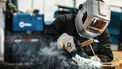
Welder qualifications and a strict adherence to welding procedures are both critical to quality. “Tolerances of the fitup of the joint, the cleanliness of the joint, preheat — all of those things will lead to weld quality problems if you don’t follow correct practice,” says Miller. “Field erection is a tough business. We are constructing buildings where we measure the perimeters in feet or thousands of feet. But when it comes to weld joints, we are talking about sixteenths of an inch. That’s a tough thing to control.”
John Leisner, product manager, Miller Electric, emphasizes that a welding procedure specification (WPS) and welder performance qualification (WPQ) are the foundations for quality. “WPS determines through testing that the weld being made will serve its intended purpose. WPQ is used to determine if the welder himself has the skill required to perform the weldment,” he says.
Having a written procedure is an important recipe for success. “It is used to define the variables involved with producing a sound weldment,” says Leisner.
The WPS covers amperage, wire feed speed, travel speed, pre-heat, post-heat, filler metal classification, etc. “If there is something left to guess, there is something wrong with the procedure.”
Once you ensure that the welders are qualified and you have well-defined welding procedures in place, the attention turns to the actual welding equipment. Storage and use of filler materials
When you stick weld with low-hydrogen electrodes, such as the E7018 Series, you must be aware of proper handling and storage procedures. “The flux coatings on the outside of these rods are hydroscopic,” says Leisner. “It basically wants to soak up all of the humidity that is around it.” This results in increased hydrogen levels, which can cause cracking in the weld.
For this reason, these electrodes should never be left lying around on the jobsite. The solution is strict adherence to welding codes. “If you are welding to the codes using a SMAW electrode, the codes usually spell out time tables for exposure, and the limitations you have for exposure and in rebaking/reprocessing the electrodes if they have been overexposed,” says Dean Phillips, manager of welding engineering, Hobart Brothers Co.
Storage and handling of tubular FCAW- and GMAW-electrodes designed for low diffusible hydrogen levels is a whole different issue. “Most of the codes are not black and white on tubular wire storage as compared to SMAW electrode handling and storage,” says Phillips. “Most of the codes will have some suggestive recommendations, but typically say ‘follow the recommendations of the manufacturer’. If you buy a tubular electrode with low diffusible characteristics, ask the manufacturer if extended exposure data is available and how to store and maintain the electrode.” Proper voltage and amperage
Manufacturer-recommended voltage and amperage ranges for filler materials also deserve close attention. “With flux-cored welding, I have noted that some people don’t pay attention at all,” notes Leisner. For instance, consider a self-shielded wire recommended up to 220 amps. “You will walk up and it may be at 300 amps. Since it is a voltage-sensitive wire, you may be changing the chemical composition of the deposit. You may not reach the desired mechanical properties because you poured too much energy into it.”
The manufacturer provides all of the necessary parameters. “Typically, you will see a voltage and a wire-feed speed recommendation, and you may see an amperage recommendation,” notes Leisner. “When you are outside of those parameters, you really don’t know what is going to happen.”
But with proper testing, operating outside of the manufacturer’s recommended parameters is not always a problem. “As long as the fabricator/erector has tested a PQR test plate, and the test results meet the requirements and are accepted by the EOR (Engineer of Record), it is fine,” says Phillips. “The fabricator/erector may operate outside the manufacturer’s recommendations.”
However, this is not the case when using prequalified welding procedures, such as in the D1.1 code. “If the fabricator/erector is using prequalified welding procedures, then that is another story,” says Phillips. “The fabricators/erectors not only must stay within the manufacturer’s recommendations, but be within all of the code prequalified requirements and conditions.”
If you are using voltage-sensitive wires, it is important to maintain the recommended electrode stick out. Too much or too little stick out may cause weld discontinuity and possible defects.
Voltage drop in the cables is another issue that can lead to poor weld quality. “Some people will call in and try to figure out why they can’t get enough power to where they are welding,” says Leisner. This is when the question of lead length often comes up. “They may say it is 100 ft. and we ask, ‘Is that 100 ft. one way or is it two ways?’ ”
There is a difference between the length from the machine to the work and the lead length. “What we want to find out is the distance from the positive electrode to the work and back to the machine,” says Leisner. That is the complete weld circuit. “A complete weld circuit is what helps us determine how much voltage drop they will have in the cables. The longer the cables, the more resistance, which is why selecting the proper size cable is so important.”
Other common causes of voltage drops include increased resistance from poorly kept leads and old leads where some of the copper strands might have been broken. Select for the task
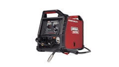
What you plan to do with the welder has a major influence on the correct machine for your application. “Typically, with a self-shielded flux-core wire process, we want to use a CV (Constant Voltage) type machine,” says Leisner. CV machines are suited for voltage-sensitive wire.
But Leisner reports that he still sees some people welding voltage-sensitive wire with CC (Constant Current) type machines. “The reason that scares me is if we have a constant current power supply, that means the voltage is allowed to fluctuate. If you change your arc length a little bit, your voltage changes. Your risk of defects increases significantly when you use CC vs. CV.” There are a lot of power sources that are capable of doing both.
Some newer machines can also increase weld quality vs. older units.
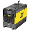
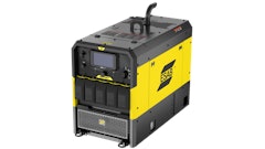
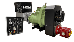
Feedback circuits on modern engine-driven welders compensate for changes in the environment. The power characteristics of older machines would actually change as they warmed up. “Certainly, with the modern equipment that should not be a restriction,” says Miller. “With today’s technology, you can certainly get very similar types of output and control as what you would have for the shops.”
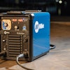
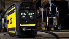
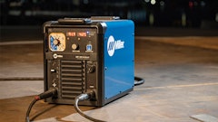
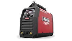
If you have steered away from inverters because you had a bad experience in the distant past, take another look. Inverters promise many advantages in the field. “Perhaps the first advantage is that they are smaller, lighter weight and more portable,” says Miller. They are also more energy efficient, and the ability to control the output characteristics of the inverter is outstanding.
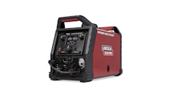
“We can get better arc transfer, lower spatter and overall better weld quality with the inverter-based machine designs today vs. the previous inverters and, more importantly, vs. the conventional transformer/rectifier machines,” says Miller. “If you have typical 60-Hz, three-phase power, when you rectify it, you have 360 signals a second that you can play with in terms of manipulating the output.”
Inverters operate at 20,000 Hz and more. “Instead of having 360 signals a second, you have tens of thousands of signals,” says Miller. “With high-speed switches, we can chop those signals up and build them into wave shapes.” This allows you to more effectively build the kinds of output characteristics that are ideal for metal transfer, Miller adds. “That is where pulse welding and wave shape controls are going,” he states, “giving the arc the power when it needs it and backing off when it doesn’t need it.”


