Answer: This is not an uncommon issue in the marketplace and contractors need to understand the basis for the concern as well as the information that can assist the commenter in moving forward with comfort or finding an appropriate solution. Aside from the obvious conflict in the relationship, this inquiry is one of proper, minimum and acceptable footing projection dimensions. In order to clarify the concern for the owner and help them move forward in this project, a look at the current building codes is important.
The International Residential Code (IRC)1, as this column has discussed in the past, is the reference most utilized by designers, contractors and code authorities throughout the U.S. Depending on the state or jurisdiction of adoption, variances in the effective IRC edition and possible modifications applied to that base code exist. In short, the prescription for footing design and construction in the IRC moves quickly from a basic and simple concept to a potentially complex or confusing adaptation of construction technology and system support.
 As shown in the 2015 International Residential Code (as well as previous versions) foundation walls are shown on footings and bearing directly on soil, Figure R403.1(1).International Residential Code
The IRC opens the discussion of footings with a general statement of requirement (R403.1), applied to the structural support of residential structures that could be slab-on-ground; built on a crawl space; or incorporating a full lower living level or basement. Here it states:
All exterior walls shall be supported on continuous solid or fully grouted masonry or concrete footings, crushed stone footings, wood foundations, or other approved structural systems which shall be of sufficient design to accommodate all loads according to Section R301 and to transmit the resulting loads to the soil within the limitations as determined from the character of the soil. Footings shall be supported on undisturbed natural soils or engineered fill. Concrete footing shall be designed and constructed in accordance with the provisions of Section R403 or in accordance with ACI 3322.
It is important to understand that a formed concrete footing is not a general requirement in order to adequately distribute the exterior wall loads of a residential structure conforming to the IRC; one- and two-family dwellings of no more than three stories above grade. While this is the section on footings, at the very basic level, exterior walls for a residential dwelling must be supported effectively to the soil condition in a manner sufficient for the classification of that soil. In the language of the IRC, crushed stone is just as acceptable for bearing as a concrete footing. In fact, later in the IRC the user will find prescriptive requirements for precast and wood foundation walls most often bearing on gravel footings. In effect, a concrete foundation wall can be supported on a gravel footing with these same confinement specifications as well as the concrete wall bearing directly on the soil, provided the contact with that soil is of sufficient width for the soil bearing capacity.
It is a fact of code development that minimum provisions follow proven construction practice. Therefore, the cast-in-place concrete or grouted masonry foundation walls, which have historically desired a concrete footing for the consistent and clean surface it provides, become prescriptively related to concrete footings while precast and wood foundations are related to gravel footings. It is important to note, although, that such gravel footings are restricted to seismic zones A, B and C only.
Next, the IRC prescribes the geometry for a footing in section R403.1.1.
The footing width shall be based on the load-bearing value of the soil in accordance with Table R401.4.1. Footing projections, P, shall be not less than 2 inches (51 mm) and shall not exceed the thickness of the footing.
 Table 401.4.1 as printed in the 2015 International Residential Code.International Residential Code
The footing width, no matter the construction type, is governed then by the soil bearing capacity. Soil types range from very poor capacity or low load-bearing pressure as found in sandy, silty and weak clays (1,500 psf) to very high capacity as found in crystalline bedrock (12,000 psf). The weight of the residence transferred through the structure ultimately accumulates to a total load at the contact point with the soil. When compared to the prescribed or tested bearing capacity of the soil, the footing width is then increased until sufficient width equalizes the load to the capacity. Tables in the IRC provide a quick determination of the minimum width and thickness of the concrete footing but at no point in any table is the concrete footing less than 12 in. wide nor less than 6 in. thickness.
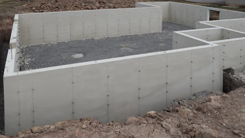
As noted in detail 6 above, the bearing width of a foundation wall may be sufficient to support the loads on the given soil. However, most concrete foundation walls are actually formed on concrete footings. The IRC prescribes an absolute minimum footing width of 12 in., which is a result of concrete and masonry walls (those most often using concrete footings) having a common minimum width of 8 in. plus the minimum projection of 2 in. on each side, thus the 12-in. total. The owner in this inquiry comments on the deviation of the location of the wall to the footing, thus challenging the consistency or equivalence of the minimum projection (P). As a concrete footing is excavated or forms constructed and ultimately concrete placed, it is possible for the exterior or interior line of the footing to become altered. As long as the minimum width is maintained, as prescribed by the code or shown on the prints, the performance of the footing for load transfer will be effective. ACI 332 (noted earlier from IRC section 403.1), states in its prescription:
7.2.1 Wall footings
7.2.1.1 Wall footing width shall be at least the greater of the applicable dimensions specified in Tables 7.2.1.1a through 7.2.1.1h or the supported wall thickness plus 4 in.
This code does provide further commentary on the minimum projection dimensions as a practical way of supporting the forming system, an answer to why the 4 in. of extra thickness is established:
R7.2.1.1 Footing widths need to project a minimum of 2 in. on each side of the wall to support the forming system. The footing width projection is measured from the face of the concrete wall to the edge of the footing.
ACI 332 brings further relevance to this discussion by referencing ACI 1173 for construction tolerances. General and application specific tolerances for foundation systems are found in this code-referenced document, where section 3.2—Deviation from Location, states:
Where the foundation dimension is less than 8 ft, .greater of +/-2% of specified dimension or 1/2 in.
ACI 117 then provides section 3.5—Deviation from cross-sectional dimension of foundation, in which the effective width of the footing or foundation is given a tolerance. Those are:
Formed Foundations
Horizontal deviation………+2 in., –1/2 in.
Unformed Foundations cast against soil, horizontal deviation from plan dimension. Excavation shall be measured before concrete placement. Tolerance shall apply at all locations.
Where dimension is 2 ft. or less ...........................+3 in., –1/2 in.
Where dimension is more than 2 ft. ......................+6 in.–1/2 in.
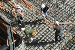
 A forming crew worker checks the square on a foundation set. Variations in the actual line of the set wall forms on the footing are possible when final measurement checks are made.Concrete Foundations Association
It is therefore acceptable for an IRC-prescribed minimum concrete footing of 12 in. (w) x 6 in. (t) with projections of 2 in. to be allowed tolerance to a width range of 11.5 to 15 in. with a minimum projection of 1.5 in. The IRC also states that the projection cannot be greater than the footing thickness, in which case a plan tolerance here would permit the maximum project ion of 6 in. to be as great as 9 in. without being reinforced (seismic zones A, B and C only).
Construction and forming accuracy are an important aspects of a solid quality assurance program for professional concrete companies, no less so for those whose markets are primarily residential or agricultural. Acceptability in code minimum requirements and applied tolerances should not be an excuse for a lack of commitment to such quality assurance, however, they should also not be used as leverage by a home owner, builder or code authority for the purposes of claiming incompetence.
References:
- 2015 International Residential Code® For One- and Two-Family Dwellings published by the International Code Council, Inc., 4051 West Flossmoor Road, Country Club Hills, IL 60478-5795 | Phone 1-888-422-7233 | www.iccsafe.org
- Residential Code Requirements for Structural Concrete (ACI 332-14) and Commentary published by the American Concrete Institute, 38800 Country Club Drive, Farmington Hills, MI 48331 | Phone: 248-848-3700 | www.concrete.org
- Specification for Tolerances for Concrete Construction and Materials (ACI 117-10) and Commentary published by the American Concrete Institute, 38800 Country Club Drive, Farmington Hills, MI 48331 | Phone: 248-848-3700 | www.concrete.org
About the Author
CFA Executive Director, Jim Baty, participates in many discussions of construction and code application for Association members, designers and code authorities. Contact him at 866-232-9255 or by email at [email protected]. ACI documents can be obtained by contacting the CFA or by visiting the American Concrete Institute (www.concrete.org) and ordering from their bookstore.