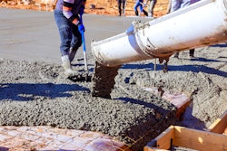
Understanding the concerns with mass concrete can help contractors avoid problems such as noncompliance, construction delays, damaged concrete and expensive repairs. Specifications for mass concrete limit fresh and in-place concrete temperatures and typically require a thermal control plan by the contractor for each mass concrete placement. Consequently, contractors must know about maximum concrete temperatures and temperature differences, temperature rise, temperature monitoring and control, pre- and post-cooling of mass concrete and thermal modeling.
Defining Mass Concrete
The American Concrete Institute (ACI) does not provide specific size limits to define mass concrete. ACI defines mass concrete as “any volume of concrete with dimensions large enough to require that measures be taken to cope with generation of heat from hydration of the cement and attendant volume change to minimize cracking.1 Historically, large placements where the minimum cross-sectional dimension equals or exceeds three feet are commonly designated as mass concrete. However, smaller sizes may also be designated as mass concrete depending on factors including: type and quantity of cement, volume to surface ratio of the concrete, weather conditions, concrete placing temperatures, degree of restraints to volume changes and the effect of thermal cracking on function, durability and appearance.
Carefully review the contract documents to identify what structural elements the specifier has designated as mass concrete. The specifier, not the contractor, is responsible for determining what concrete on the project is mass concrete. For elements designated as mass concrete in the contract documents, the additional requirements specified in ACI 301, Section 8 – Mass Concrete apply.2 If the documents are not clear, then request clarifications before work begins.
Maximum Temperature & Temperature Differences
To avoid concrete damage, specifications limit the maximum internal concrete temperature and the maximum allowable temperature difference between the center and surface of a mass concrete element.
ACI 301 states:
1) The maximum temperature in concrete after placement shall not exceed 158 degrees Fahrenheit
2) The maximum temperature difference between center and surface of placement shall not exceed 35 degrees Fahrenheit.
Limiting the internal concrete temperature to 158 degrees Fahrenheit prevents delayed ettringite formation (DEF). Ettringite is a normal product of cement hydration that forms within the first few hours after batching the concrete. Early-age high temperatures (greater than 158 degrees Fahrenheit) can prevent the normal formation of ettringite. If DEF occurs in hardened concrete with an external moisture source, internal expansion with subsequent visual displacement and cracking may occur. DEF can also increase the risk of additional deterioration due to freeze/thaw attack and reinforcement corrosion. Limiting the internal temperature during the concrete’s very early life will prevent DEF.
 Place temperature sensors at center of the mass concrete and at a depth of two-inches from the center of nearest exterior surface. Take readings every hour and compare concrete temperature and temperature difference to specified maximum limits every 12 hours.
The specified 35 degrees Fahrenheit maximum temperature difference between the center and the surface of the concrete minimizes the potential for thermal cracking. The temperature difference is the difference between the temperature measured at the center or hottest portion of the concrete and the surface.
The thermal gradient between the center portion and the surface creates tensile stresses in the concrete. Essentially, the interior portion is expanding relative to the surface. This differential expansion creates tensile stresses. When the tensile stresses exceed the tensile strength of the concrete, cracking occurs. The depth and severity of the cracking depends primarily on the magnitude of the thermal gradient.
The 35 degrees Fahrenheit maximum temperature difference is a historical value and may be conservative for today’s concrete's and designs. Differences of 45 degrees Fahrenheit or even 55 degrees Fahrenheit may be sufficient to control thermal cracking. Increasing the maximum temperature difference can save time and money. The maximum temperature difference depends on many variables that control both the thermal stresses and tensile strength of the concrete. For these reasons, it is becoming common practice to use sophisticated computer-based thermal modeling to determine the maximum allowable temperature difference so the thermal stresses do not exceed the tensile strength of the concrete.
Temperature Rise & Predicting Maximum Temperatures
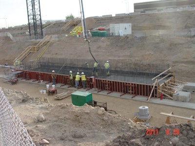
Factors such as type and amount of cementitious materials, concrete placing and ambient temperatures, size and volume to surface ratio of the concrete element control the temperature rise and maximum temperature in mass concrete. In general, only concrete elements where the minimum cross-sectional dimension equals or exceeds three feet have thermal concerns because smaller elements typically dissipate the generated hydration heat at a rate sufficient to limit temperatures to required levels. Thicker elements do not dissipate hydration heat at a fast enough rate and temperatures at the center of the pour can therefore build to levels that exceed specified levels.
 Heat removal by cooling pipes depends on location, size and spacing, flow rate and temperature of the chilled water. Cooling pipes must be pressure grouted after the cooling period ends.
Two methods commonly used to predict the maximum concrete temperature include an approximate “equivalent cement content” method and computer or thermal models. With the approximate method, estimate the maximum temperature by adding 16 degrees Fahrenheit for every 100 pounds of cement per cubic yard to the concrete placing temperature. For Types F and C fly ashes and slag cement (50 percent replacement) use 50 percent, 80 percent and 90 percent of the equivalent cement per cubic yard, respectively3 Essentially, this method assumes that these materials generate 50 percent, 80 percent and 90 percent of the heat as compared to cement. [For an example, see chart.]
Thermal Control
Methods to control the concrete temperature and temperature difference include:
Concrete mixture - Limit the quantity of cement to the smallest amount possible and replace cement with slower setting supplementary cementitious materials (SCM) such as Class F fly ash and slag cement. Use cement with moderate to low heat of hydration properties. Do not use Type III or HE (high-early strength) cements and chemical accelerators. If available, use low thermal expansion aggregates such as granite, limestone or basalt. Slowing the rate of heat generation also slows the rate of strength gain. Therefore, propose a 42- or 56-day compressive strength for concrete acceptance in lieu of the standard 28-day strength.
Work with the concrete supplier to develop an economical and low-heat generating concrete. Run trial mixes in the laboratory to establish fresh and hardened concrete properties. Perform field tests by casting blocks to represent the mass concrete elements and measure internal and surface temperatures. Also, use the test blocks to evaluate the proposed concrete placing techniques and the post-cooling plan. Be sure the measured temperatures comply with the specified temperature limits. If not, revise the thermal control plan.
Reduce concrete placement temperature – ACI 301 does not specify a maximum concrete placement temperature for mass concrete but specifiers commonly use 50 degrees Fahrenheit and 70 degrees Fahrenheit. As illustrated in the example calculations for estimating the maximum concrete temperature, the maximum concrete temperature is a function of the placement temperature. If the placing temperature had been 50 degrees Fahrenheit in the example, then the estimated maximum concrete temperature would have been 131 degrees Fahrenheit. In general, every degree of precooling reduces the maximum concrete temperature by approximately one degree. Pre-cooling or reducing the concrete’s placing temperature can reduce both the concrete temperature and temperature difference.
Pre-cooling - Means to pre-cool concrete include shading and sprinkling the coarse aggregate pile with water, using chilled mix water, replacing mix water with shaved or chipped ice and injecting either the mix water or fresh concrete with liquid nitrogen. In general, pre-cooling the aggregates by 2 degrees Fahrenheit will cool the fresh concrete by about 1 degrees Fahrenheit. Direct and evaporative cooling lowers the aggregate temperature. Temperatures within about 2 degrees Fahrenheit of the wet bulb temperature can be achieved by blowing air through the moist coarse aggregates.
Reducing the mix water temperature by 4 degrees Fahrenheit will cool fresh concrete by approximately 1 degrees Fahrenheit with a maximum temperature reduction of about 10 degrees Fahrenheit. Substituting shaved or chipped ice for mix water (up to about 75 percent) can reduce the fresh concrete temperature up to about 20 degrees Fahrenheit. Of course, the amount of pre-cooling will depend on the amount of mix water available for ice substitution.
When the specifications limit the concrete placement temperature to 50 degrees Fahrenheit or more than a 20 degrees Fahrenheit concrete pre-cooling is required, consider using liquid nitrogen. With an injection temperature of -326 degrees Fahrenheit, fresh concrete temperatures as low as 35 degrees Fahrenheit are achievable.
Post-cooling - Use insulation to control the maximum temperature difference between the center and the surface of the mass concrete. Slowing the rate of heat dissipation from the surface reduces the temperature difference and the potential for thermal cracking. Of course, reducing the cooling rate of the concrete may cause construction delays. Wet curing is risky because the thermal shock from applying cool water to hot surfaces may cause rapid cooling of the surface and cracking.
 Use thermal modeling to estimate both center and surface temperatures vs. time. Comparing temperatures vs. time charts yield the maximum temperature difference between center and surface of concrete.
Thermal Modeling
As part of the thermal plan, consider using computer-based thermal modeling to estimate the maximum concrete temperature and temperature differences. In addition, modeling can evaluate and optimize the pour size (lift or block size), placement schedules (time intervals between placements) and temperature control plan to minimize the risk of thermal cracking. Computer modeling is a quick and efficient way to evaluate the different options available for controlling temperatures and thermal cracking. In most cases, the cost of the modeling is insignificant to the potential savings from optimizing the thermal control plan.
References
1. ACI 207.1R-05 (2012) Guide to Mass Concrete, American Concrete Institute, www.concrete.org
2. ACI 301-10 Specifications for Structural Concrete, American Concrete Institute, www.concrete.org
3. Gajda, John, Mass Concrete for Buildings and Bridges, Portland cement Association, 2007, www.cement.org
For additional information:
ACI 207.1R-05 Guide to Mass Concrete
ACI 207.4R-05 (2012) Cooling and Insulating Systems for Mass Concrete
ACI 207.2R-07 Report on Thermal and Volume Change Effects on Cracking of Mass Concrete
About the authors
Kim Basham is president of KB Engineering LLC, which provides engineering and scientific services to the concrete industry. Basham also teaches seminars and workshops dealing with all aspects of concrete technology, construction and troubleshooting. He can be reached via e-mail at [email protected].
L. J. Mott, PE, is president of GES Tech Group, Inc., which provides general mechanical, structural, civil, and forensic engineering services to a wide variety of clients and industries. Mott is an expert in advance finite element modeling, specializing in non-linear static and dynamic mechanics and transient thermodynamics. He can be reached via email at [email protected].