Information from this article was first published in Demolition Magazine and is being reused with permission from the National Demolition Association.
In 2012, CALTRANS decided to remove and replace aging steel truss and box girder bridges that cross the San Joaquin River in California with a newer design which was capable of carrying three to four lanes of traffic in each direction. Fresno, Calif., Kroeker Inc. was the demolition contractor for the job.
The San Joaquin River is a major tributary to the California Delta water system, providing a natural boundary between Fresno and Madera counties in Central California. A primary North/South highway that runs through the interior of California crosses the San Joaquin River.
At the intersection lies a series of bridges, spanning over 825 feet dating back to 1929. A second crossing to accept growing traffic flow was installed later adjacent to the original span. The same steel truss concept used on the first bridge was used on the second.
Since the construction of the second span, the California Department of Transportation (CALTRANS) designed and built another major highway, I-5, to the west of the San Joaquin Valley to reduce the amount of traffic along the Highway 99 corridor. In 1987, CALTRANS strengthened and replaced the older bridge, while widening both bridges and installing a barrier rail system.
A newer style bridge was installed between the two steel truss designs known as a concrete box girder design. Even with the widening, the roadway was still only used as two lanes in each direction.
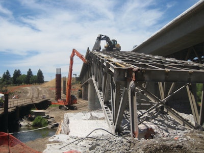
The bid called for the removal to be performed without affecting the river flows or disturbing the river bed. After the start, the “in river” work was determined to be water areas only. This reduced the amount of protection required to the river bed areas, meaning that nothing was to be allowed to fall into the active river section. To assure this, a protective cover was engineered to span the river and provide protection for the entire footprint of the bridge, plus 10 feet on either side of the structure.
Eighty-foot steel beams supporting a timber deck were placed across the river to provide for collection of any debris that may fall during removal operations. The protective cover was not designed to carry any significant loads, and any debris that did fall on it was removed each shift or more often.
Where the truss section was over the active river, a crane and hand labor was used to cut the steel into manageable pieces. As soon as the river section was completed, the protective cover was removed to allow the general contractor access the area for his new pier sections.
The construction of the truss was made up of an 8-inch concrete deck over 16-inch longitudinal beams at 5-foot centers spanning every 16 feet to a 36-inch transverse girder. This girder in turn was supported by the truss design. The members of the truss were a basic 14-inch H-pile design attached to the top and bottom longitudinal chords, measuring 24 inches tall running the full span. The top and bottom chords were over 1 inch thick and in some cases over 2 inches thick.
The removal operation called for splitting the staggered pattern over each longitudinal structural member. A penetration at one end was made to facilitate the use of a 75,000-pound class Link Belt excavator for the removal. The bucket was able to go through the deck between the longitudinal beams where upward pressure allowed the excavator to pull the entire 5 foot-by-16-foot section each time. The Nelson Studs gave little resistance, and where there was resistance the deck was folded on top of the remaining section.
It was determined the rebar in the deck was an essential component in supplying lateral support to the truss design. The deck material was spun off the excavator behind the operation and pushed off the span being removed then loaded and hauled from the area for recycling.
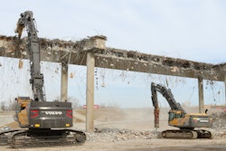
Once each 156-foot span of deck was removed, a layer of 10 mil plastic was spread over the river bed to catch and contain any paint chips developed during the shearing operations. A Komatsu 650 excavator equipped with a G130 Allied concrete breaker was used to attack the support piers of the truss section.
The support piers were removed by taking the center mass out first leaving only the attachment area, also known as a hinge. The areas under the truss support hinges were then chipped simultaneously, allowing the entire end of the truss to fall to the ground. Once one end was on the ground a Volvo 490 excavator equipped with a LaBounty 4000R shear was positioned back on the deck of the next remaining span. A Hitachi 450 high-reach excavator was positioned adjacent to the span as support and assistance for the Volvo. Now the entire span was on the ground and stable.
A major concern with the stabilization was the unknown of how the truss would react when certain truss components were cut. It could not be determined if the entire span would be unstable if a miss-cut occurred. With the span being completely on the ground, stability was not an issue. The 4000R shear was then repositioned to shear the entire span for loading. Each span had over 200 tons of steel processed.
The operator and excavator were able to process an entire span in just over one day. This process continued for six spans. With the learning curve out of the way, the crew was able to process an entire span in less than a week. Once past the river, Kroeker Inc. moved out of the general contractor’s way, which allowed them to proceed on schedule.
There are still two bridges left to remove due to staging of traffic. The next removal will entail the removal of the box girder section which is planned to be accomplished from the other truss bridge first. The protective cover over the river will first be accomplished using the bottom deck of the box girder as the initial cover while removing the concrete deck. Then a cover similar to the previous one will be installed to capture debris from the remaining sections. Once the box girder is removed the next truss section will be demolished.
Kroeker has generated over 2,000,000 pounds of structural steel and over 3,000 cubic yards of concrete all while following stringent requirements to serve as a steward of the environment and protect the river bed.